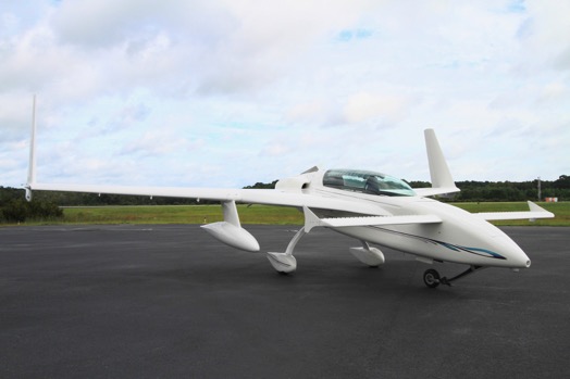
Sadly, today I am starting to market my plane. I have already had a few calls from interested buyers for Cloud Dancer. I have decided to put all the pictures here with details on the plane to highlight all the features and special additions to the plane. A few years ago I rebuilt and restored the plane which you can view on this blog starting here: Start of rebuilding N29TM
After being in this sport for 25+ years I really dont think there is a finer EZ out there and none with the ‘one of a kind’ features and additions I have added to the plane. I hate selling it, but I have a Cozy 4 project almost completed and its time to move on to a new plane.
Baggage pods are included.
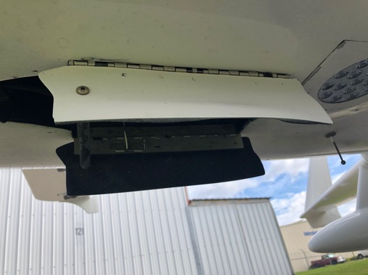
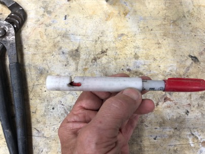
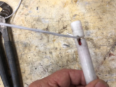
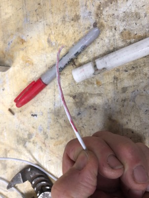
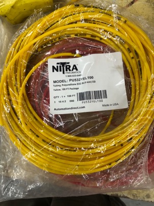
The Nose compartment where I usually carry tie down equipment, a tool bag and my travel cover. There is a placard for canard removal. All pitot and static tube is color coded. Red, pitot and yellow is the static system.
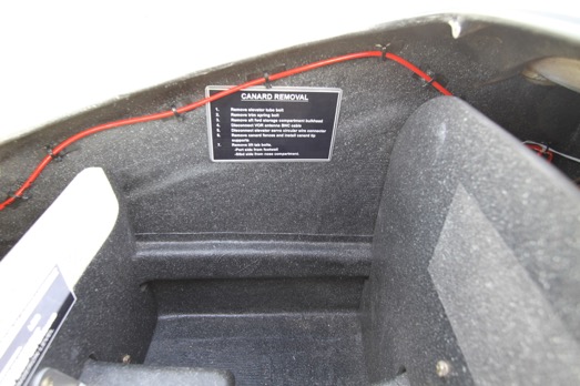
A warning placard which tells the pilot the nose MUST have enough ballast in its to stay on the ground when the plane is level. You will then be within the CG envelope.
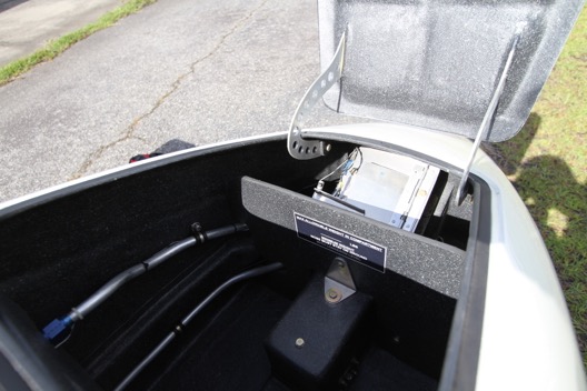
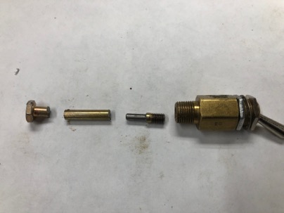
The compartment has bulkheads fore and aft to prevent interference with the control system. On the right you can see the Ram Heat system heater. I have a lot of information about concept of Ram Heat that I
developed on this blog, Here is an additional article I wrote for CSA about Ram Heat: Ram Heat Article
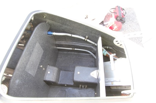
The compartment can actually quite a bit of stuff, as long as you stay within the CG range.
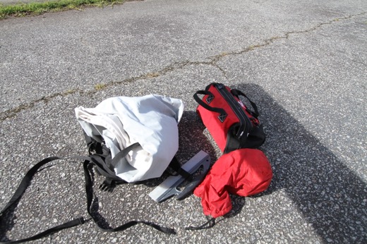
This is what I usually have in the compartment.
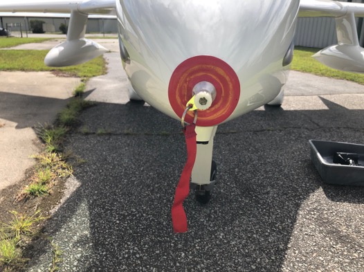
The Ram Air Heat inlet has a cover which attaches to the pitot tube when parked outside.
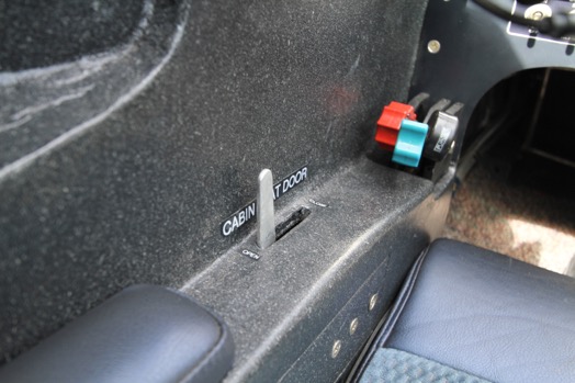
Nose gear doors.
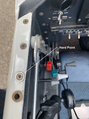
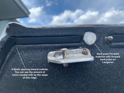
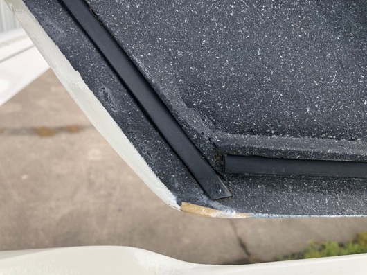
The seals for the canopy are in a molded track using LongEZ V seals. They seal the canopy with ZERO air leaks and no forced compression.

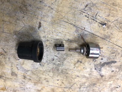
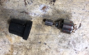
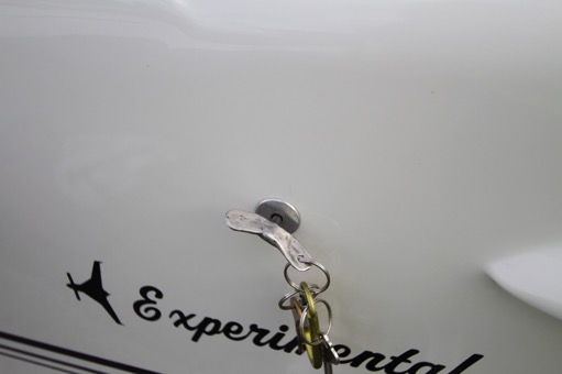
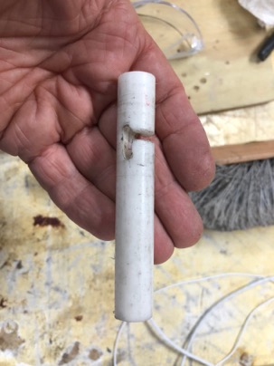
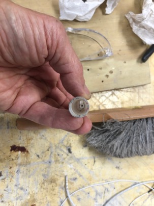
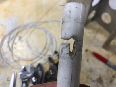
The canopy is secured by a rotary latch system.
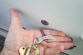
The key for the canopy.
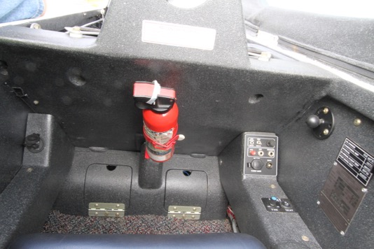
The fuse panel is located under the pilots seat for easy access. I have not had a fuse blow since I wired the system .
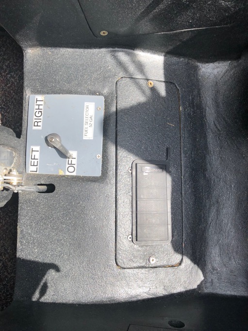
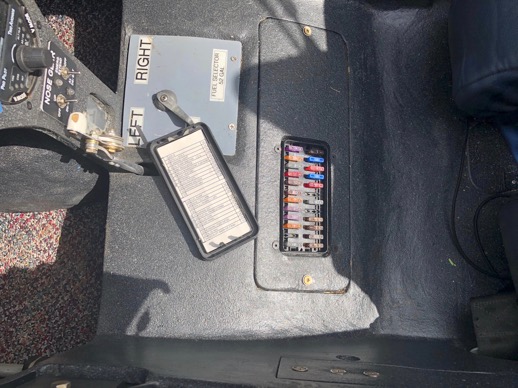
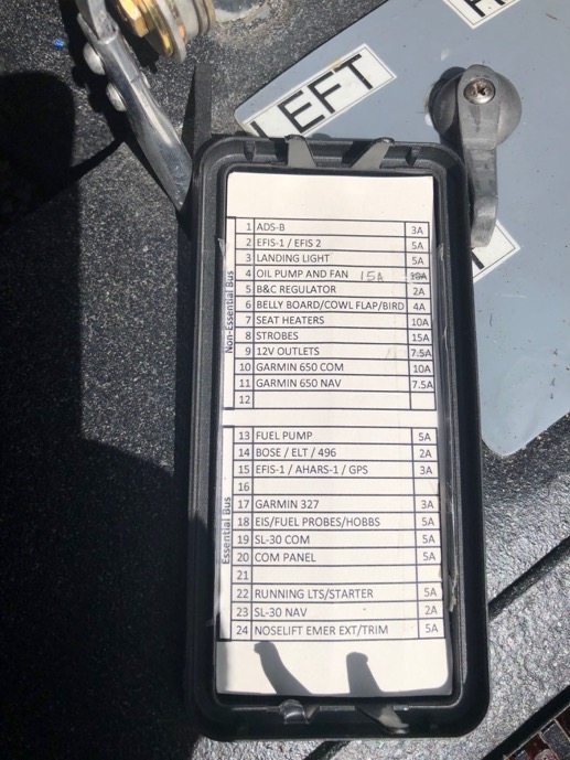
All fuses in the essential and non-essential buss are labeled.
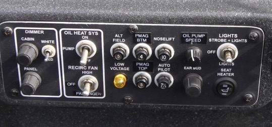
Heater control to close the air door of the heater air outlet when initially taking off on a cold day. After your engine oil heats up, turn on the pump, open the heat door for cabin heat.
Side panel for additional storage of a few items.
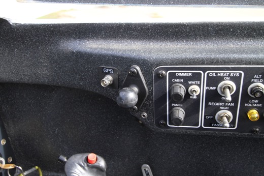
LED lighting (white or red) on a dimmer control for the pilot. 12 v outlet (switched).
Two usb outlets are available for the pilot. I have it set up for 2 Apple Lightening connectors to keep my iPad and iPhone charged in flight when using ForeFlight.
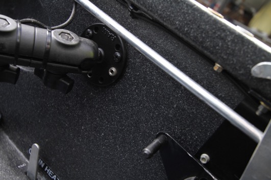
Ball mounts are located on the port and stbd sides. Each one has a 1/8” connector wired to the Comm panel for music input. This side mount has a BNC connection to a GPS antenna when I use my Garmin 496 attached to the mount..
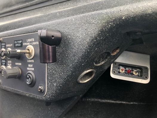
Notice on the panel the Oil Heat Sys pump switch and below the switch is the Recirc Fan switch, which allows the pilot to turn on the rear heat fan in fast speed select the “Passenger control” of the fan which allows the passenger adjust the temperate in the rear off the plane.
Port ball mount with stereo plug input
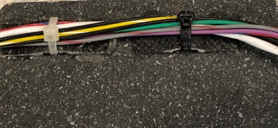
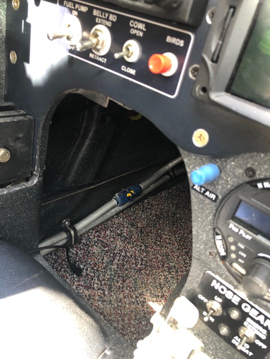
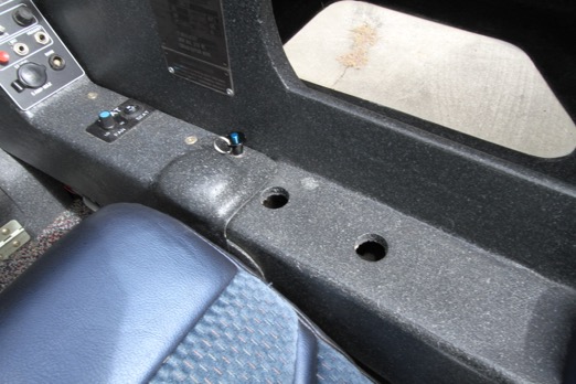
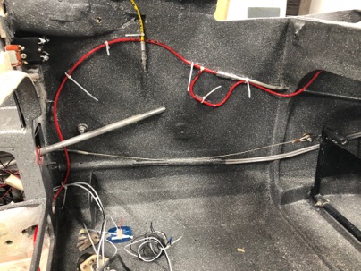
I hate looking at footwells and seeing LOTS of wires. It makes the plane look so unfinished.
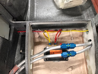
On the port side there is a fixed wire chase to hide the wires
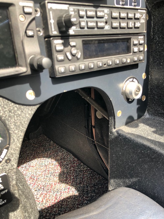
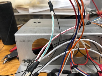
On the STBD side the wiring chase has a removable cover for the wires. Antenna wires are separated to prevent cross talk.
Along with controlling the heater pump speed (which controls the temp of the heater output) there is a seat heaters in the cushions (Pilot and passenger). I rarely use it as it quickly heats your butt up and normal only use it for a little while to warm up the comfort foam seats on a cold morning..
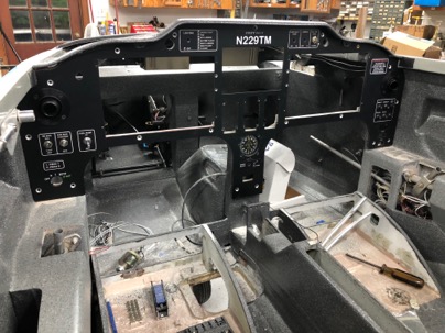
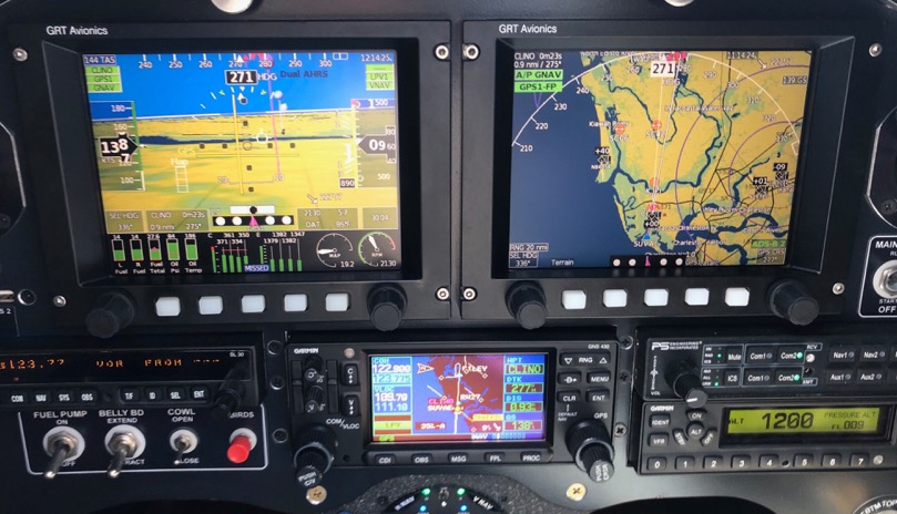
The Dash
Dual air outlets coupled to the COLD side of the Ram Air inlet. They are very quiet in flight. I like cold air on my face when my legs and body is warm to keep me awake.
Dual Grand Rapids 6” HX displays.
Garmin SL-30
Trio Pro-Pilot Autopilot coupled to the displays via ARINC 429, or you can run it independently
Garmin 327 Transponder
NavWorx ADS-B IN and OUT
PS Engineering audio panel
The Garmin navigator allows for full IFR flying. You can do coupled to the autopilot via GPS, ILS or VOR approaches.
Wilhelmson nose lift with automatic extensions (the AEX option).
Electric belly board.
Bird beeper.
Dual USP inputs for each EFIS to allow for a mapping USB stick input for Seattle Avionics mapping data to be input to the EFIS’s.
ACK Dual frequency ELT. It transmits on 406 MHz and 121.5 MHz frequencies and provides position accuracy with the optional GPS input connected to the Garmin radio.
Picture of the dash while doing a coupled GPS approach into my local airport.
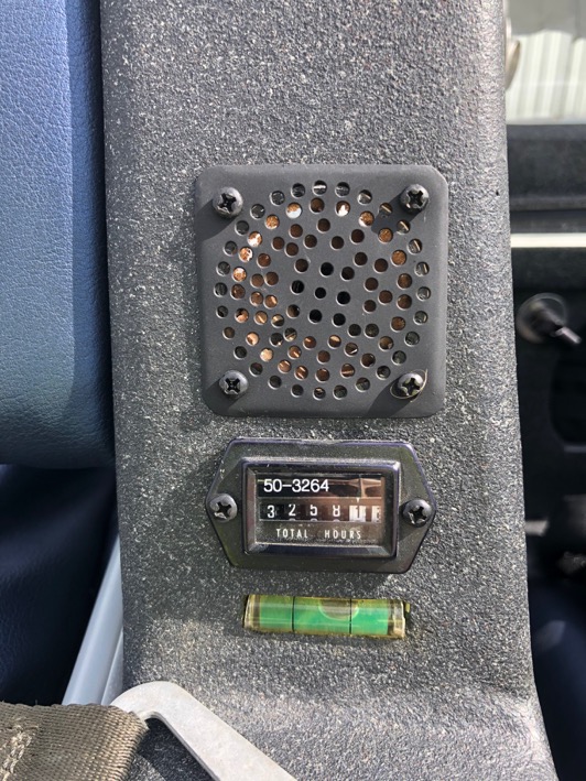
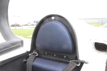
The head rest has the hour meter, speaker and a level to to be sure you you dont flip the plane when parking on a non-level surface and for accurate fueling indications.
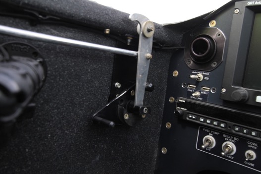
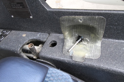
There is an additional cover the rear stick to prevent interference of the control system when packing out the back of the plane. You can also see rear strake windows.
The stick cover is removable and the pin is used to secure the control stick when needed.
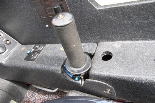
Stick installed and wired into the Comm PPT system.
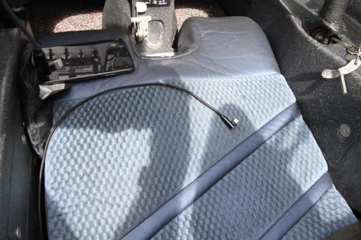
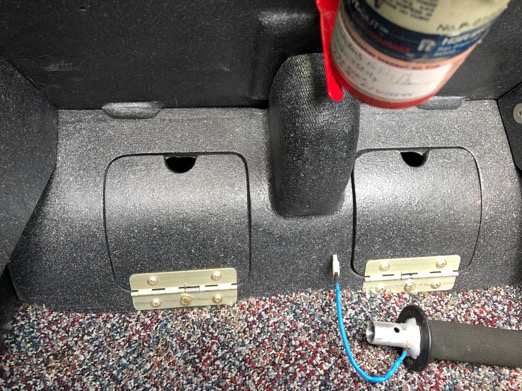
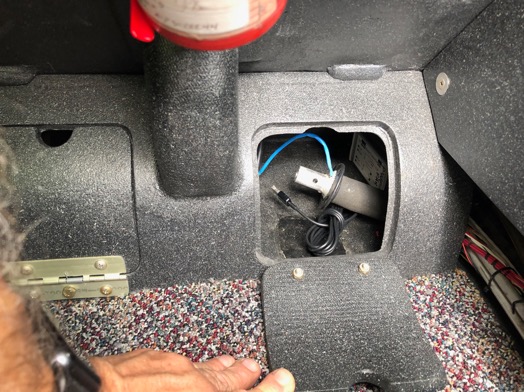
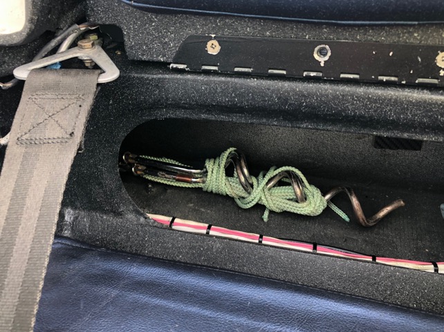
When not in use the control stick is stored in a foot rest compartment for the passenger. It utilizes the space effectively and is more comfortable for the passengers feet.
The passenger has side panel installed on the port and STBD sides to cover the control system. There another USB outlet on the port side panel. You can see the ball mount for the rear passenger to mount an IPAD or other device.
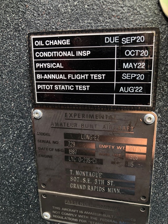
This is how I keep track of key dates I need to be reminded of.
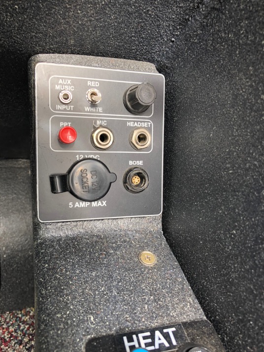
Passenger panel for music input, lighting control, headphones.
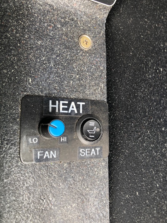
Rear heat control for the fan and seats.
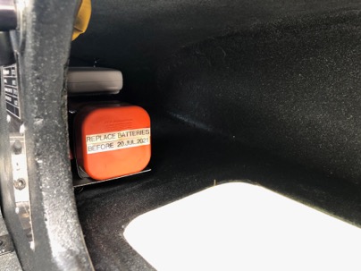
ELT Battery replacement reminder.
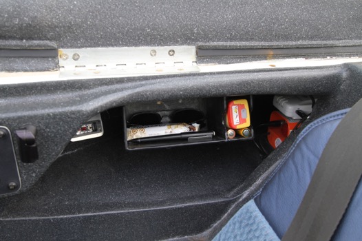
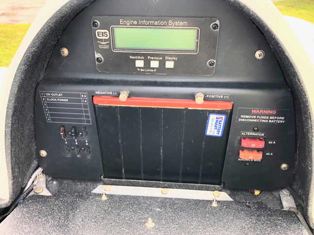
The rear headrest covers the electronic bay.
Behind the head rest cover is the Odyssey PL680 Battery, GRT 4000 engine monitor, starter solenoid, MAP sensor, fuses, Princeton fuel level capacitance modules.
The spar box is also used for additional storage.
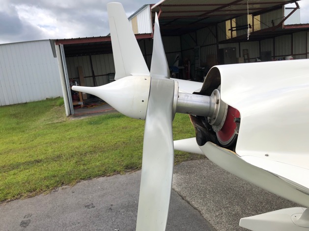
The business end… The prop is a Gary Hertzler Silver Bullet which has be dynamically balanced with the ACES balancer. I have a ring on the prop to allow for easy attachments of weights.
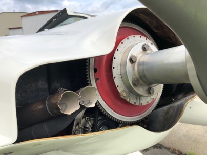
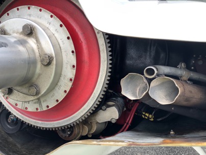
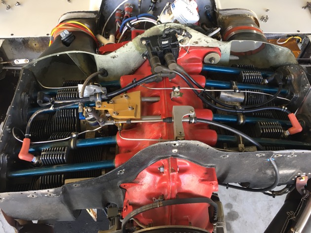
IO-320 with AirFlow Performance fuel injection. 9.1 compression pistons, port and polished cylinders. Dual PMags (114 series). Fuel flow (injectors) have been balanced to allow aggressive lean of peak operation.
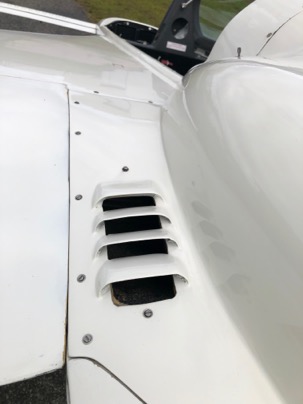
Cylinder cool very well.
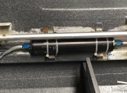
Additionally, there is a Reiff engine pre-heat system installed. Reiff Website It heats both the engine oil and the cylinders with the 50 watt band heaters. If you have electric in the hangar, you can preheat the engine on a timer so when you arrive at the hangar on the coldest winter day, the engine oil and cylinders are hot. You can go to full power immediately after startup.
With preheated oil, you’ll get cabin heat from the Ram Heat system as soon as you get in the air. I usually preheat the engine before a flight. When I arrive at the hangar the engine oil is already at 115f, cylinders are at 140f. After engine start, on taxi, I close the ram heat door, turn on the seat heaters to warm up, and turn on the oil pump. When the oil temp indicator at the heater starts to increase, I open up the ram heat door, and turn off the heater. It only takes 1 or 2 minutes. I love having cabin heat before i leave the pattern.
The cowl has cam lock fasteners and no screws. This is the oil cooler outlet. My oil runs a 175f all the time. I never see it any higher.
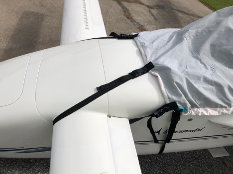
Bruces LongEZ travel cover.
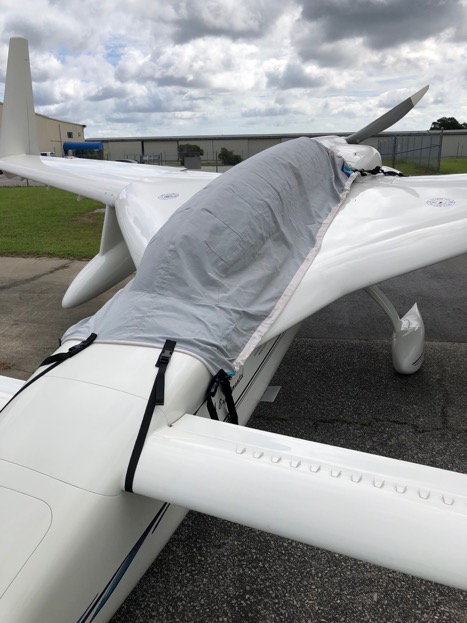
I had Bruces modify it with additional straps (which are essential) to keep it pulled forward when you cinch up the back of the cover on the trail edge of the wings.
Performance
A screen shot at 13000 ft. TAS 162 kts @2460 rpm, OAT 40f, 6.2 gph. Cylinders running between 325-354f
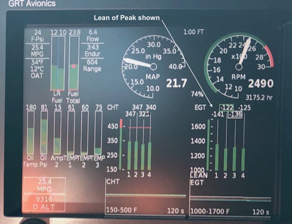
Lean of Peak Operation
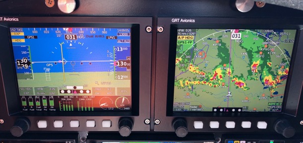
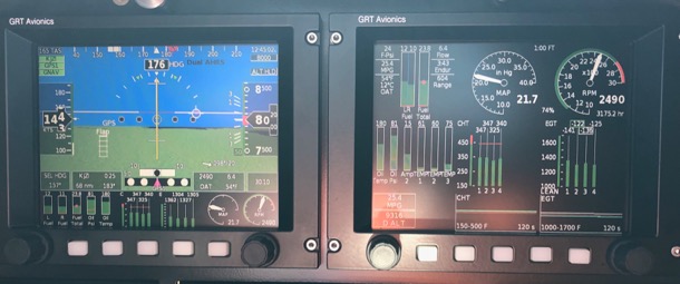
8000 ft. TAS 165 kts @2490 rpm, OAT 54f, 6.4 gph, Cylinder 325-347f.
The is an enlargement of the Stbd EFIS panel above. You can see the engine is operating at an amazing 122-141 f Lean Of Peak operation while still cruising at 165 kts. This indicates exceptional well balanced fuel injector restrictors. Who needs GAMInjectors?
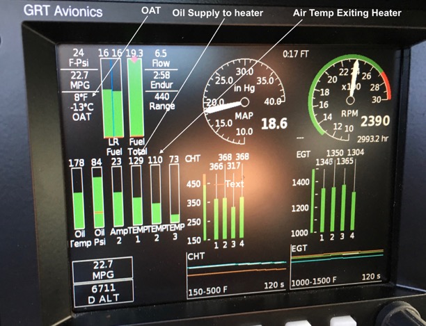
Cabin heat
A shot of the heat system in operation while flying home from PA. OAT 8 deg F, Temp1 is the temperature of the oil supply (129f). Temp2 is the air temp of the air exiting the heater (110f). Temp3 is the temp of the rear seat area. This data indicates there is a 102f temp differential across the cooler (OAT@8f- Temp2@110f).
Obviously, I was very comfortable at 8f on this flight with no jacket, gloves or wearing no special cold weather gear. i was wearing a long sleeve shirt and jeans. The plane had zero air leaks around the canopy and no fogging of the canopy since the cabin is being flooded with hot dry air. This is the advantage of Ram Heat.
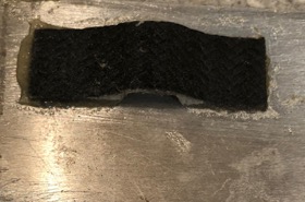
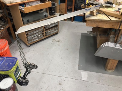
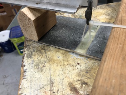
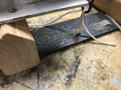
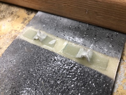
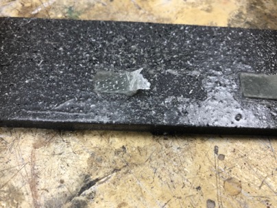
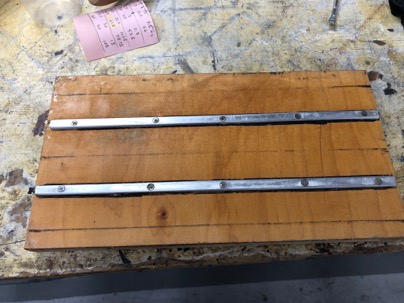
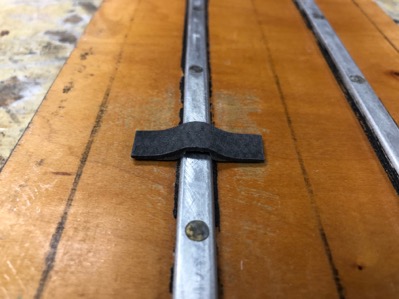
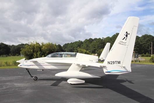
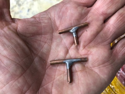
Canard Fences
Here you can see the canard fences I developed and tested. I have been using these on the plane for over 7 years and they really increase the plane’s ability to handle of cross wind landings with canard aircraft by essentially increasing the effectiveness of the rudders. Fences increase lift on the canard while also allowing the plane to easily take off in heavy cross winds without scalping. I am the only canard that I know of that has them installed and will have them on any canard that I own in the future..
I gave a presentation at the Rough River Fly-in which discusses the benefits of canard fences on how and why they work. adfgsdfg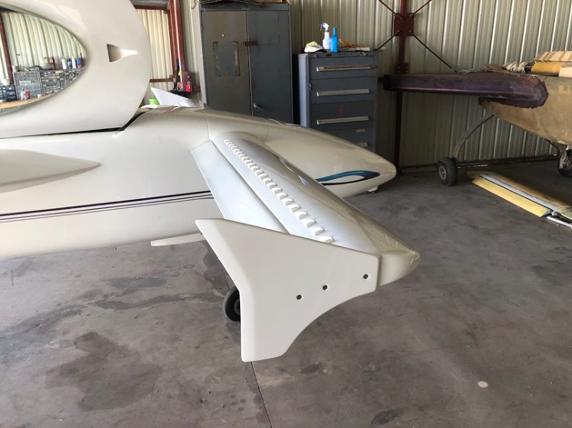
 ’
’