Nov 30 2012

Spice Rack

Todays project was to try and organize all my commonly used spices in my kitchen

wpid-CIMG1844-2012-11-30-21-01.jpg

This is the area where I decided to add some custom shelving.

wpid-CIMG1843-2012-11-30-21-01.jpg

A quick trip to the hangar to cut and bend some pre-painted aluminum I had and I shortly ended up with some nice shelves.

wpid-CIMG1847-2012-11-30-21-01.jpg

The finished product… Now I can have quick access to my commonly used spices and I also made a rail to hang my big spoons and ladles.

wpid-CIMG1870-2012-11-30-21-01.jpg

Nov 28 2012

O-Ring Oil Leak Reduction Modifications

One of the good things about doing this engine overhaul is that I can renew my efforts to get rid of oil leaks. I will replace all my self made oil hoses with the newer teflon with SS brad type and again try to seal the gaskets in such a way to reduce oil leaks. As most owners, it is our goal to have ZERO oil leaks. With this old lycoming technology it is a bit difficult to achieve.

Where possible, I have made a few mods (thank your experimental aviation!) to reduce oil leakage points.  A search on the internet resulted in the design guide from Parker O-ring company and I was able to learn quite a bit about how to properly machine an o-ring grove. The ones which I originally machined into a few parts were not correctly made. This may be why my first attempt at sealing was less than successful.

wpid-CIMG1838-2012-11-28-21-001.jpg

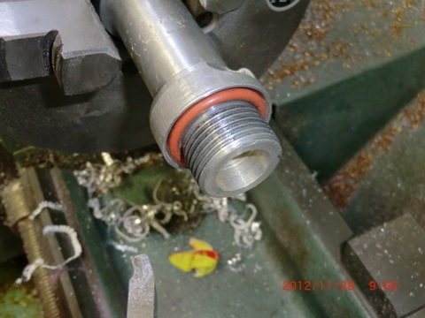
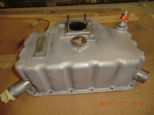
First I corrected the o-rings groves machined into the oil dip stick extension tube I made for my down draft cooling plentums.

Next it was machining an o-ring grove into the oil temp sensor to replace the copper crush seals on the B&C oil filter.

wpid-CIMG1899-2012-11-28-21-001.jpg

This is the oil temp probe with the 1/16” Viton o-ring. A little research shows Viton to be one of the best oil ring materials for the fluids in our planes.  For oil, 100LL, brake fluid Viton has the best chemical properties. I am glad I looked this information up as the old Brock gas caps o-ring seals always give me problems with sealing. Now I know why, I was buying the wrong type material for the o-rings and mo-gas would cause them to swell. I have to go to the hangar tomorrow, so I’ll get some new ones for the bird and replace the ones which are on it now.

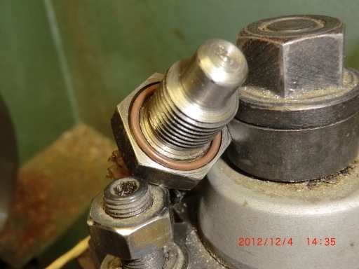
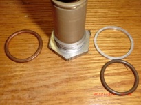
For the vernitherm, you can see the crush ring on the left and the o-ring/spacer ring on the vernitherm

wpid-CIMG1904-2012-11-28-21-001.jpg

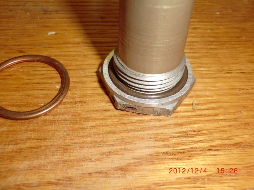
Crush rings do work… sometimes, but I don’t trust them. Since there was limited room to work with on the vernitherm , a  pressure ring was machined (to allow proper crush of the o-ring) to contain the o-ring.

I was concerned about the proper positioning of the the vernitherm element as It has to be the right distance from the seat to work properly so I didn’t want to machine the cap (even if I could have).

wpid-CIMG1902-2012-11-28-21-001.jpg

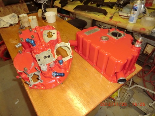
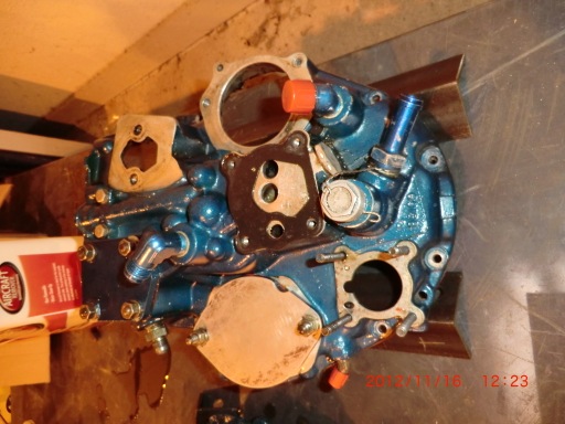
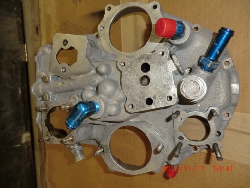
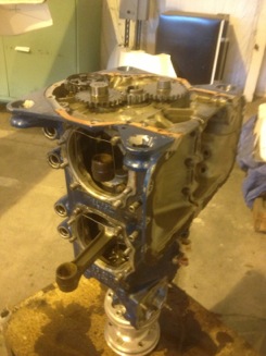
For the accessory case, I tapped and installed a plug in an unused oil gallery used to mount the pump for the controllable pitch prop governor..

wpid-CIMG1894-2012-11-28-21-001.jpg

This way the gasket should not see any pressure at all. Again, no o-ring could be used

.wpid-CIMG1910-2012-11-28-21-001.jpg

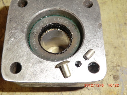
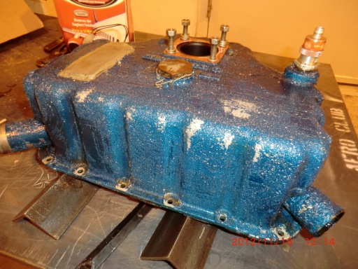
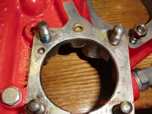
For the vacuum pump pad, there was a small port which is used for lubrication of a “wet” type vacuum pumps. Since we are using “dry” pumps this oil gallery again could be plugged. I used a large rivet, cut the head off, and inserted it into the hole with sealant and crushed it place to make a solid aluminum plug to keep oil pressure from being applied to the vacuum pump gasket.

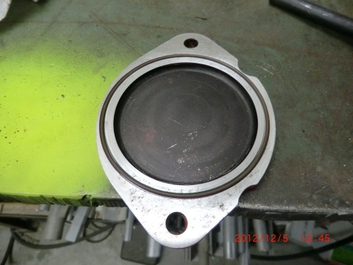
Lastly, an o-ring grove was machined into the plate used to seal the unused mag hole,

wpid-CIMG1916-2012-11-28-21-001.jpg

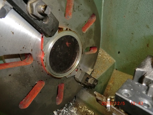
No gasket is needed.  Such a simple operation!  I don’t know why the covers dont come pre-groved.

wpid-CIMG1917-2012-11-28-21-001.jpg

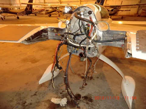
I only hope that the effort into making these mods makes a difference on the oil leaking on the engine. Should be interesting to check out when I get the plane back into the air.

*Update: Feb 2012-  The mods were successful!  I didnt have any oil leaking from any of the changes I made.

I did find oil leaks at the flare fitting of the hoses.  Apparently, the AL fitting, even though they are anodized, can be easily scratched or damaged thus causing leaks.  I had to lap the end of the hoses into the fitting to eliminate the scratches.  In the future, I’ll only use steel fitting for any oil/gas line on the engine.

Nov 21 2012

Engine Case Stripping

The process was repeated for the engine case.

wpid-CIMG1818-2012-11-21-21-47.jpg

Case stripped in about 1.5 hrs work

wpid-CIMG1821-2012-11-21-21-47.jpg

Primed…

wpid-CIMG1533-2012-11-21-21-47.jpg

Finally painted! Moving along!

wpid-CIMG1543-2012-11-21-21-47.jpg

Nov 19 2012

Engine Plentum Box Upgrade

I took the the opportunity while I had the engine apart to upgrade the DD cooling box.

When I originally made the Down Draft cooling box years ago, it was completely made of fiberglass/carbon with small Al inserts to reinforce holes. This approach didn’t work so well as you can see because the heads would get up to 400-450f and was destroying the glass/Alum attachment points. I could never properly torque the bolts and they were always loosening up on me.

wpid-CIMG1792-2012-11-19-21-52.jpg

The fiberglass is just disintegrating!

wpid-CIMG1795-2012-11-19-21-52.jpg

I have been an advocate lately that one should use Al where appropriate and easy to incorporate, and not use glass in high temp areas. The decision was made to make a hybrid DD cooling box to smartly use Al on the heads and glass everywhere else.

The DD cooling box was cleaned in my dish washer. A couple of wash cycles sure cleaned things up!!

wpid-CIMG1783-2012-11-19-21-52.jpg

template was made to cut out the Al replacements for the head area.

wpid-CIMG1793-2012-11-19-21-52.jpg

The parts were cut out in Al.

wpid-CIMG1798-2012-11-19-21-52.jpg

Here you can see the old and new head attachment areas. I really like the new style head attachments as the bolts can be properly torqued and the Al can handle the high heat of the heads.

wpid-CIMG1801-2012-11-19-21-52.jpg

New paint and the rebuilt DD box looks good and will now work for the life of the plane with no issues.

wpid-CIMG1806-2012-11-19-21-52.jpg

wpid-CIMG1803-2012-11-19-21-52.jpg

Nov 17 2012

Painting the oil pan

Today was spent taping and paint the oil pan. I love the look of Zinc Chromate primer. It has a wonderful yellow green color. You can easily pick it up at the local West Boating Store.

wpid-CIMG1776-2012-11-17-21-42.jpg

After the spray painting was done, I just brushed on the enamel engine paint. The color is almost exactly the same color of the valve covers. It will really look good when fully assembled!

wpid-CIMG1788-2012-11-17-21-42.jpg

Sweet!

wpid-CIMG1808-2012-11-17-21-42.jpg

Nov 16 2012

Accessory Case Stripping

Today was spent stripping the paint off the cases. Actually it turned out to be very easy to do with some Rustoleum Aircraft Paint stripper I purchased from the local auto parts store.

The oil pan

wpid-CIMG1770-2012-11-16-21-361.jpg

wpid-CIMG1773-2012-11-16-21-361.jpg

The accessory case.

wpid-CIMG1772-2012-11-16-21-361.jpg

wpid-CIMG1774-2012-11-16-21-361.jpg

Nov 16 2012

Paint stripping

Today was spent stripping the paint off the cases. Actually it turned out to be very easy to do with some Rustoleum Aircraft Paint stripper I purchased from the local auto parts store.

The oil pan

wpid-CIMG1770-2012-11-16-21-36.jpg

wpid-CIMG1773-2012-11-16-21-36.jpg

The accessory case.

wpid-CIMG1772-2012-11-16-21-36.jpg

wpid-CIMG1774-2012-11-16-21-36.jpg

Nov 13 2012

Engine Removal day 2

Today I got the engine hoist and prepared for the pulling the engine from the plane. Finally it is off.

wpid-CIMG1700-2012-11-13-19-50.jpg

Next step is disassembly.

I started off going to the metal shop to pick up the material to make a case splitter. An aircraft engine does not use a gasket between the case halves. It uses a sealant which essentially glues the cases together. You MUST use a splitter to get the case apart.

wpid-CIMG1696-2012-11-13-19-50.jpg

I had come up with a workable design and made a case splitter years ago and after using it, was loaned it out to a buddy. Unfortunately, he lost half which required me to have to make a replacement.

Surprisingly, when I googled “lycoming case splitter” I only came up with one hit on how to make one. It was my OWN website! I had completely forgotten that I had posted pictures and details on the web. Making a new one was easy and only took a few hours to complete.

After building the splitter it was off to the airport to begin disassembly of the engine. I made a quick engine stand to to hold the engine up vertically, and got to work.

wpid-CIMG1699-2012-11-13-19-50.jpg

By the end of the day, the engine was torn down and ready to be split. I’ll do that tomorrow.

wpid-IMG_3789-2012-11-13-19-50.jpg

I think I am going to strip off the blue color and repaint the engine in red. I need a change.

Nov 12 2012

Engine removal day 1

I spent all day just taking the accessories and wires off the engine. If I could ever make a worth while recommendation to someone doing an engine installation, it would be to focus on future engine removal when you are doing the installation. How can you make it as easy as possible to remove the engine because eventually it will happen so plan ahead.

My plane is not the easiest to work on. I really didn’t know much at the time I built it so the way I layered the wiring, hoses, accessories, baffling, etc is not as well planned out as I would like. When I upgraded N123LE, I made sure removing the engine would be as easy as possible and could easily do so in about 2-3 hours. On my plane It took me most of the day to prepare it for removal.

wpid-CIMG1690-2012-11-12-19-41.jpg

Lots of parts for sure.

wpid-CIMG1692-2012-11-12-19-41.jpg

Nov 11 2012

Fuel Servo Install

As soon as I returned from Myrtle Beach, I installed the rebuilt fuel servo on the plane and took her up for a test run.

Tweedy started better than ever and I now have plenty of power and can easily get 2700 rpm. I did a full power run and got up to 182 kts true at 1500 ft. Sweet.

wpid-CIMG1680-2012-11-11-18-47.jpg

The only problem is the vibration issue hasn’t changed. Still got it.

I have been fighting this issue since my return from my “western” tour trip. I have rebuilt the the electronic ignition systems (overhaul of the Pmag, replacement of wires and coils), replaced the Lightspeed coils, replaced the plugs, replaced one of the cylinders, replaced the engine mount, overhauled/replaced the hydraulic lifters, did compression tests, wobble test, checked everything I could think of, had the engine off the airplane twice, and nothing has made a difference.

The engine went from running great to having a noticeable vibration in one night. When I landed in Santa Fe, it was running great. When I took off the next mooring, I had a vibration which I instantly noticed. After almost 3 months of trouble shooting, I have finally made the decision to just take the engine off and rip it apart to have all the internal components inspected and rebuild the lower end.

If after rebuilding the engine if I still have a vibration, I will know there is absolutely nothing wrong with the engine, it will not self destruct on me and I will just have to live with the vibration.

Tomorrow let the fun begin.