Category: LongEZ Repair

Jan 19 2018

PMag Blast Tube

A requirement for a PMag installation is the addition of a blast tube on the base to assist in keeping the unit cool. Since PMag does not sell an adapter, it forced me grab some scissors and create a template. It took little time and is very light weight.

Here is two orientations I needed for both of my PMag.

IMG_9049-2018-01-19-16-21.jpg

Here is a very easy design to cut and bend the adaptor which insures the air is directed into the cooling grill on the bottom side of the unit.

IMG_9037-2018-01-19-16-21.jpg

After bending the metal (.015” AL) a tube was riveted on and all was sealed with a bit of RTV.

IMG_9048-2018-01-19-16-21.jpg

Enjoy.

http://nickugolini.com/blog/wp-content/uploads/2018/01/BlastTubeforPMag-1-19-18-2018-01-19-16-21.pdf

Mar 21 2016

Building Tips: Epoxy Brushes

Here is a building tip for your epoxy brush.

I use a cheap Harbor Freight brush and just throw it away when done. Gone are the days of trying to clean a brush.

The problem is: A paint brush makes for a louse epoxy brush. Many times you are left to pick up the brush bristles which come off and it is not very good for stippling the fiberglass to wet it out. This is mainly due to the bristles be designed for painting not epoxy work.

wpid-IMG_4321-2016-03-21-15-41.jpg

The tip is to just cut off the tip for a square end!

wpid-IMG_4322-2016-03-21-15-41.jpg

The shorter the bristles are near the handle the stiffer the brush is for epoxy work. The added benefit is I rarely find orphan bristles on my work.

Feb 20 2016

Bridge Sanding/Micro spreading Board

Rarely do I get excited about sanding micro. Especially when it comes to sanding complex curves (curves in two directions such as the nose).

Rubber sanding blocks, cross sanding in different directions, leaves the potential for dips and high spots. Using a long sanding boards aligned to the leading edge of a wing just means you’ll possibly get a long low spot as you work toward the trailing edge unless you carefully angle the board from time to time which leaves the potential of creating a flat spot.

Mike, another cozy builder, turned me on to a sanding board design I have never seen before. I did some research on the net to check out the idea and the concept made amazing sense with tremendous potential. Here is the website with for basic sander design…… .
wpid-11_31_5666f870f05d3_flexisander_nakres_056111_fkk_color-2016-02-20-11-35.jpgwpid-11_8_564c7fe9257f3_ffk_056_uprava_resize-2016-02-20-11-35.jpg

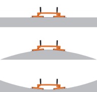
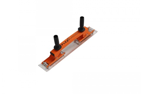
The flexible but stiff base design spreads the sanding pressure evenly over the length of an Al base when you are sanding or spreading micro on a curved surface. Basicity, it is similar to a loading bridge used to test wings for G loading. Very clever!!

Being cheap ( and not knowing how well it would work) I decided to make one for testing. Yesterday I build a couple of flexible bridge boards which turned out to be fantastic for both spreading micro and sanding curved surfaces. I had been using a 10” wide sheet rock mud knife for spreading micro on my wings…. Never again!

All I can say is I love my new sander. It sands curved surfaces perfectly and insures a nice smooth radius since the base is ridge but flexible.. On the nose, it will easily conform to the radius. On a wing you can sand perpendicular to the wing’s Leading Edge and the base will follow the curve of the airfoil to take out any high spot (from traditional sanding), highlight the low spots and will never create a flat spot.. It blew me away when I tried it on a wing.

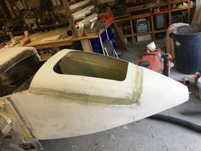
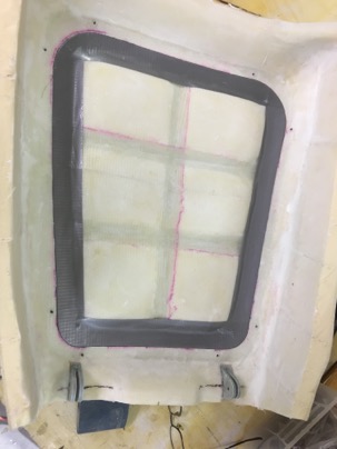
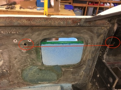
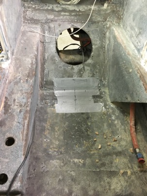
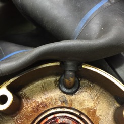
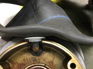
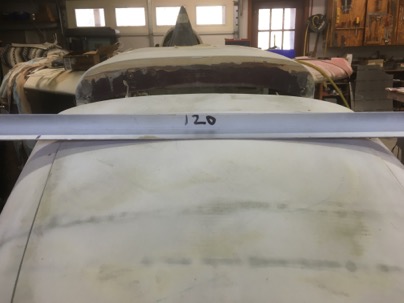
This is the curve on my nose door. It is very hard to sand to a smooth nice radius this area since the surface curves in two directions.

Front view of my nose using a traditional sanding board
wpid-IMG_4132-2016-02-20-11-35.jpg

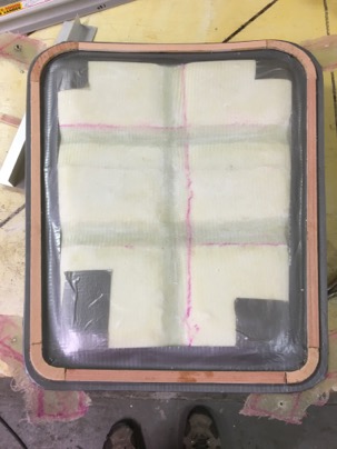
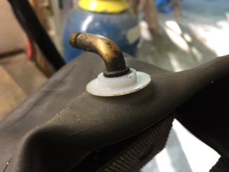
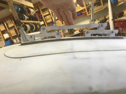
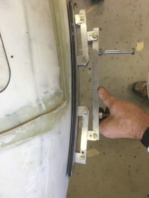
This is the bridge sander easily conforms to the surface for a perfectly curve.
wpid-IMG_4134-2016-02-20-11-35.jpg

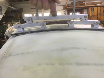
After just a few seconds of sanding, it was amazing to see how the bridge sander cleaned up the high spots from my previous sanding efforts to sand a perfect curve.

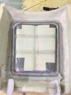
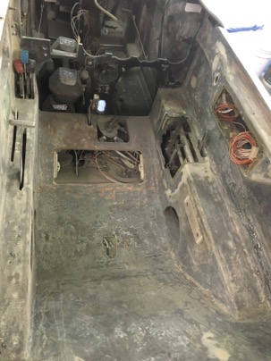
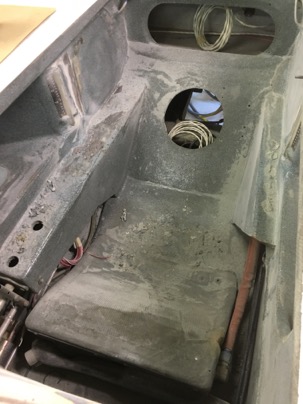
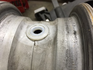
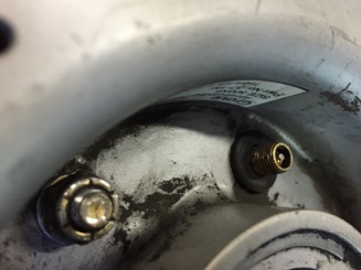
The side view of my nose hatch.
wpid-IMG_4139-2016-02-20-11-35.jpg

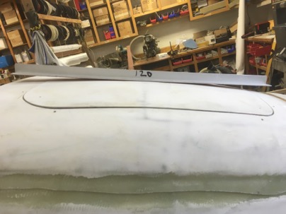
The sander curving on the nose hatch. A quick sand again highlighted all the high spots I had missed in the other direction. Sanding at 90 deg both ways forms a perfect compound curve.

wpid-IMG_4140-2016-02-20-11-35.jpg

Overall, making a ‘bridge sander’ was a very easy project (about 2 hrs effort) and most of the material you already have in the shop. AN3 bolts, and rivets. The rest of the materials are available from Lowes for around $15 (enough to make two). A 16” sanding and a 16” micro spreading bridge, or you can order a “real” 16” flexible sander for $104 and a spreading board for $95.

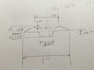
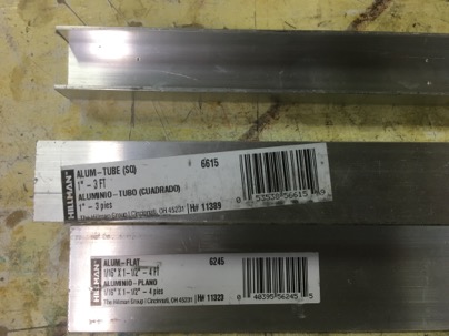
Ok, so how do you make one? Easy. Go to Lowes and buy some cheap Alum and get started. You’ll need:
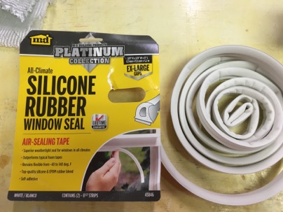
1” square tubing,
1/16” flat stock
7/8” channel (it fits inside the square tubing).
Some fasteners, whatever you have on hand and rivets.

wpid-IMG_4118-2016-02-20-11-35.jpg

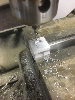
Cut 6 pieces of sq tubing about 1” long

wpid-IMG_4104-2016-02-20-11-35.jpg

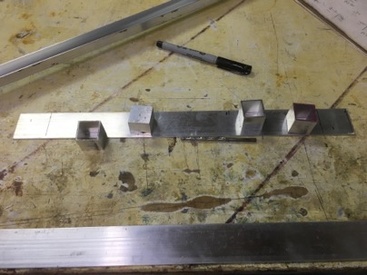
Cut a piece of the flat stock about 16” long

4 pieces: Drill a hole though both sides I used a 3/16” drill for the AN3 bolts I had on hand.

wpid-IMG_4120-2016-02-20-11-35.jpg

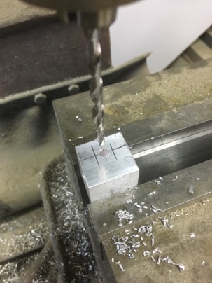
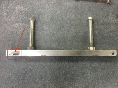
2 ea: Drill and slot the square tubes. You don’t really need a mill. Just drill a number of holes and file a slot open.

wpid-IMG_4119-2016-02-20-11-35.jpg

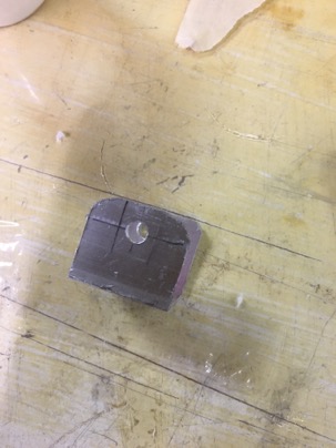
Cut the top off of all 6 pieces to create a 1” U channel

wpid-IMG_4121-2016-02-20-11-35.jpg

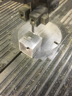
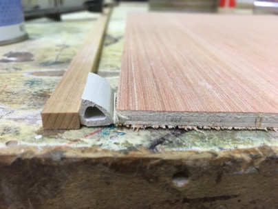
This is my practice piece… but you get the idea.

wpid-IMG_4122-2016-02-20-11-35.jpg

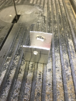
Clean it up. So now you have 6 U channel pieces, 4 with just holes, 2 with just slots. You have created a bases for the 7/8” channel to slip into.

wpid-IMG_4123-2016-02-20-11-35.jpg

wpid-IMG_4124-2016-02-20-11-35.jpg

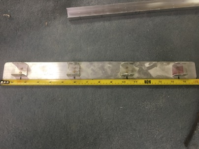
Spread the supports bases equal distance on the flat stock. I installed 2 bases (hole only) 1.5” from each end and the slotted bases 6” from each end. That is approx equal spacing along the main part of the base. You can use the 1.5” alum from Lowes, or if you want a wider board for standard strip sanding paper, use .063” AL or G10.

The bases with holes goes on each end
wpid-IMG_4125-2016-02-20-11-35.jpg

The bases with slots are in the center part of the board.
wpid-IMG_4126-2016-02-20-11-35.jpg

Use the 7/8” channel as an alignment tool so all the bases are in a straight line. Drill and rivet the bases to the flat stock.

wpid-IMG_4107-2016-02-20-11-35.jpg

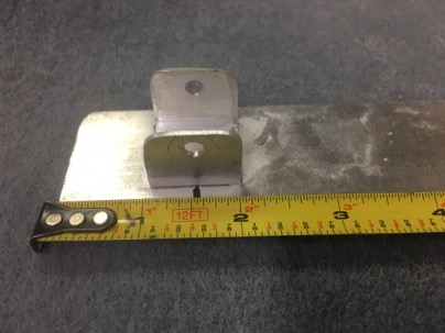
Next cut 2 pieces of 7/8” channel to bridge the distance between the the two bases at each end. Set the channels on the base and drill the cross holes for the bolts. In the slotted bases be sure to drill close to the center of the slot. If you mark and flex the board you will see how the bolt will move when the board is flexed. It will help you decide exactly where the best place is to drill the holes.

.wpid-IMG_4138-2016-02-20-11-35.jpg

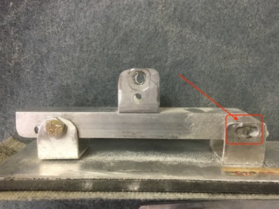
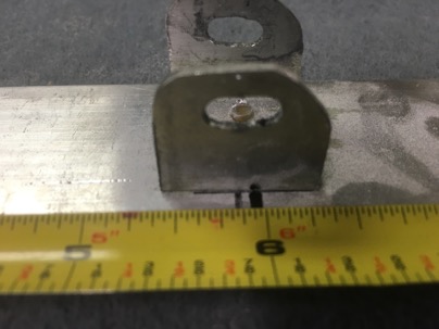
Bolt the bridges on the base and again, using the 7/8” channel as a guide for alignment, rivet the remaining U bases with a single hole in the center of each bridge.

Hint: to make it easier to drill and aline the bases, just drill through the alignment channel directly into the bases while they are in the appropriate location. Rivet a drilled base in place then work you way on to the next base, drill and rivet.

wpid-IMG_4130-2016-02-20-11-35.jpg

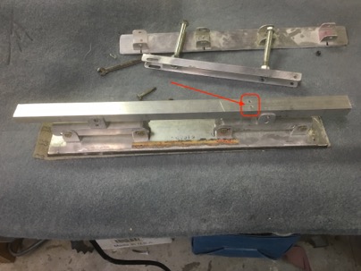
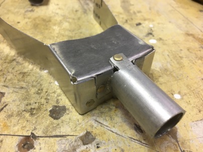
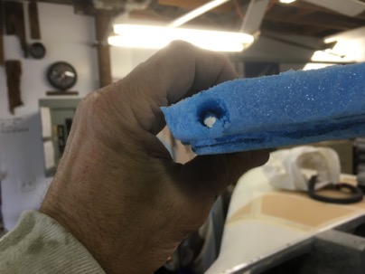
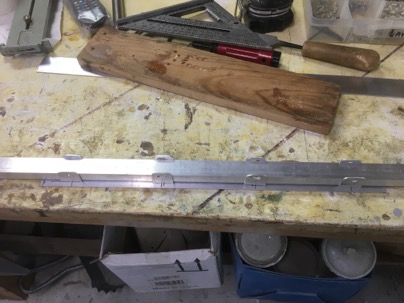
Lately cut a piece of 7/8” channel for a handle. You will have to make a long slot in one side. Again, the slot is the key to allowing the alum base to bend. In this case, drill one end, assemble, flex the board on a curved surface to mark the limits of the slot. Disassemble and mill/create a slot.

wpid-IMG_4129-2016-02-20-11-35.jpg

The handles are just 2 ea 3/8” bolts I had which are double nutted to the bar.

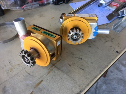
Here is the bridge sander with a micro spreading base on it.

wpid-IMG_4108-2016-02-20-11-35.jpg

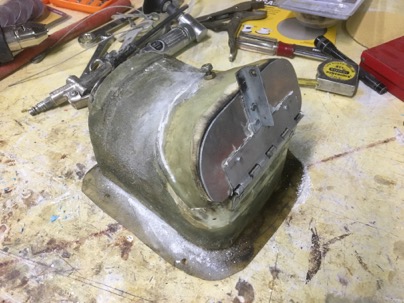
I made a second base from a crapped out in-line sander I was going to throw away. The sander base already had velcro bonded and I had velcro type sand paper on hand for it so I decided to give the sander a new life.

wpid-IMG_4113-2016-02-20-11-35.jpg

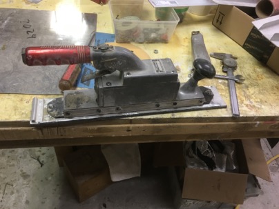
It was easy remove the turned up side edges (which made the base stiff) which then allowed the base to flex. It conveniently already had two bolts on it which is perfect for attaching the two end U channels at each end. The mod only took about 30 min to attach 4 each U bases on the sanding board.

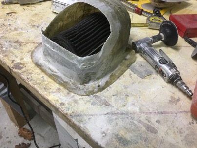
Base with side edges lip/ground off.

wpid-IMG_4114-2016-02-20-11-35.jpg

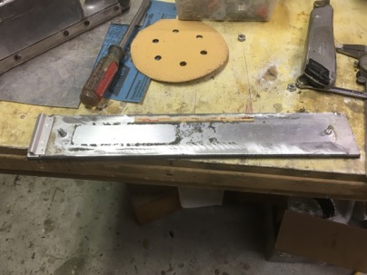
Now I can swap out the spreading board base for a sanding board base using the same handle.

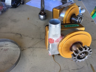
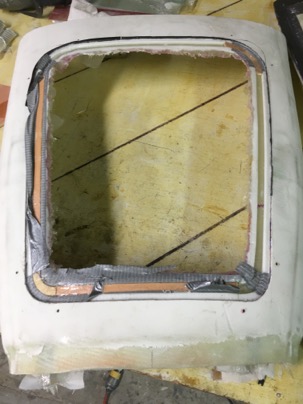
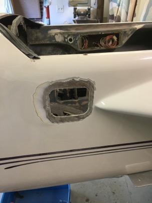
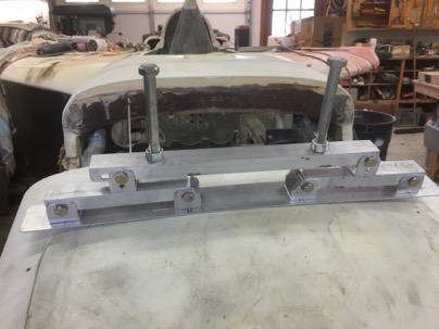
The velcro base bridge sander on the port side of the nose curving toward the tip of the plane.
wpid-IMG_4136-2016-02-20-11-35.jpg

This sander is now become an essential tool for me to quickly obtain an great finish on my plane. Once you try one, you’ll never go back to doing it the old way.

Dec 20 2015

Week Report #6

Week
                Week hours                Total hrs                Weekly average
1
2
3
4
5
6                24.6                                221                        37.0
7

Dec 17 2015

I have a door

A recap of the last few days,

The door was cut open,

wpid-IMG_3793-2015-12-17-20-32.jpg

I selected a SILICONE seal for my weather seal. I like the long lasting flexibility of silicon, and it was about the right size.

wpid-IMG_3799-2015-12-17-20-32.jpg

I found a piece of luan ply wood was the exact height I needed. The seal was roughly 0.230” high, and I wanted a crush of about 30%. The luan was exactly 0.195” which is close enough.

wpid-IMG_3800-2015-12-17-20-32.jpg

The door was taped off,

wpid-IMG_3797-2015-12-17-20-32.jpg

Luan was cut into rings (corners) and straight pieces and hot glued to the seal area.

wpid-IMG_3802-2015-12-17-20-32.jpg

All was glassed, and the next morning,
wpid-IMG_3804-2015-12-17-20-32.jpg

I had a nice door seal molded into the top.

wpid-IMG_3806-2015-12-17-20-32.jpg

Nov 17 2015

Prepping the cabin for glassing

After removing my pressurized oil heat system, I decided I NEED to do some glass work. I am tired of stripping and sanding and taking the plane further and further down the path of disassembly. I need some creative time with the bird..

This is the normal canopy hatch door that I am closing off. See the red lines. It is a wire chase I am installing for an accessory mount for my iPod at the left end. I will wire power and a stereo input thought the case. I hate to see wires and this is an easy install.

Draw a slight line, drill a hole at each end, drill a hole in the door flange and auger out the foam in between.

wpid-IMG_3406-2015-11-17-18-04.jpg

After fitting a piece of foam to close the door, drill a hole though it along the level line, Split the foam along the drill hole, stick at soda straw as a conduit, micro in the bottom and top pieces of foam and glass the door. Took all of 10 minuets to prepare

wpid-IMG_3405-2015-11-17-18-04.jpg

This is the airbag for the engine (holds the air filter).

The Door on the box was a later addition which I used to increase the cabin pressure when flying though rain.

Opening the door would to raise my normal low -50 mph cabin pressures to +5 mph cabin pressure. All the water stopped entering the cabin. I could actually feel the vents in the plane reverse direction. It is low cabin pressure which sucks ion the rain and cold. Adding more seals is just trying to fix the symptoms of the problem, without addressing the root cause.

The only drawback to my original test design was it made the cabin incredibly loud due to power pulses from the induction system having a clear path into the cabin.

wpid-IMG_3409-2015-11-17-18-04.jpg

I have a new type cabin pressurization system I have designed will address two things. Pressurization of the cabin, and improving the climate control if the cabin. If this system is successful I will duplicate it in the cozy. I learned what I needed from this successful experiment so time to be removed.

wpid-IMG_3410-2015-11-17-18-04.jpg

The door addition was cut off and box will be returned to it’s original design. Weight removed. 8 oz.

wpid-IMG_3416-2015-11-17-18-04.jpg

An area was prepared for glassing. I will be the cover for where the floor where the of the ADS-b antenna and ground plane will be installed.

Nov 15 2015

Week 1 report

Hrs: 34.
Total: 34.5

Nov 13 2015

Stripping the Cabin

I have spent the last 2 days sanding the interior. What a PITA.

I think another full day and I’ll be able to move on to fun stuff like building panels and glass work.

wpid-IMG_3397-2015-11-13-21-50.jpg

A couple more days of work and I will be done with prep’ing the interior for the beginning of the glass work.
In this area I’ll be installing the ADS-b antenna and replacing the sight glasses.

wpid-IMG_3399-2015-11-13-21-50.jpg

Preparing the door area to be closed off. I will be installing a EZNoselift.com rotary latch to get rid of the door opening.

wpid-IMG_3400-2015-11-13-21-50.jpg

Nov 11 2015

De-wiring done

Today I completed the de-wiring. I weighed just the wire alone and it came out to over 30 lbs. This doesn’t include all the instruments I took out which will be replaced by lighter equipment.

wpid-IMG_3384-2015-11-11-18-46.jpg

From a wiring nightmare,

wpid-IMG_3380-2015-11-11-18-46.jpg

to a clean sheet.

wpid-IMG_3385-2015-11-11-18-46.jpg

Not bad for a days work.

wpid-IMG_3386-2015-11-11-18-46.jpg

Basically, I have a clean plane with an engine now. The next step is to strip the interior of the existing finish, make some new interior panels and replace the sight glasses. Then re-zolatone the interior.

I am not looking forward to the dust and mess of the next step.

Apr 23 2015

Tire Valve problem Fixed

Over the years I have had a few flat tires due to the tube splitting or being cut near the filler valve on the inside of the tire. The latest time just occurred is when I flew down to FL on my way to my 2015 Bahamas trip. Fortunately I had a spare tube on board and with the help of Ed, was able to replace it in his hangar.

Additionally, most times when inflated it always seemed like the fill connection was jammed up (rotated) against the side of the rim thus making it difficult to put air into the tire.

In looking into the problem it is easy to see why it occurs.

wpid-IMG_0662-2015-04-23-16-19.jpg

There is a 5/8” hole in the rim and the rubber on the fill tube is less than 1/2”. This causes stress in on the neck of the filler tube when pressurized since it is trying to push its way out into the larger hole and at times cuts the tubes in this location. The difference in size also pushes on the fill tube into the larger hole causing it to rotate a slight amount toward the rim on the outside making it harder to add air to. The cutting of the tube has happened 3 times over the years and to many others I have talked to.

The cure is making a simple small bushing which prevents the tube from being pushed up into the rim and provides additional support to the soft rubber of the tube. You might just be able to use a large diameter washer to support the tube and keep it from pushing in to the larger hole.

Here is what they look like.

wpid-IMG_0659-2015-04-23-16-19.jpg

How the insert looks on the rim. I am sure with air pressure it presses itself flat to the contour radius of the rim.

wpid-IMG_0675-2015-04-23-16-19.jpg

For assembly, I first push the bushing the tube prior to inserting the tub into the tire.

wpid-IMG_0672-2015-04-23-16-19.jpg

With the bushing on the tube, it prevents the tube from being pushed down into the hole on the rim

wpid-IMG_0673-2015-04-23-16-19.jpg

This supports the filler tube, and keeps it from rotating keeping it straight thus making it MUCH easier for adding air.

wpid-IMG_0676-2015-04-23-16-19.jpg

No more cut tubes, easier filling. A simple fix.

This is the general drawing I used for making the nylon bushing. It is the only 1” material I had, although if the pressure distorts the bushing, I’ll make the next set of of some scrap Al I have.
The numbers are approximates so feel free to play.

wpid-IMG_0680-2015-04-23-16-19.jpg