Todays objective is to take my fuel injection system to Spartanburg, SC (about 200 miles away) to have they equipment tested. I think there is something wrong with it and some sort of fuel restriction caused my fuel emergency landing on Friday.
The trip started with a trip to do my civic duty…. Vote. I vote at the entrance to my subdivision which make the process quick (normally). Arriving at 6:45 I thought the line would be short, but alas it was quite long with a bit of rain.
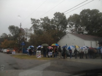
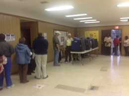
Part of the reason for the long line was they only had 4 freaking voting machines in the building! It took an hour for the voting process, and I left Charleston at 7:45 for the 200 mile drive.
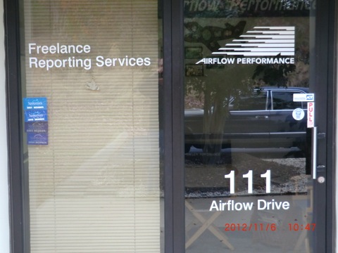
I arrived at Airflow Performance about 11 am for my meeting with Kyle.
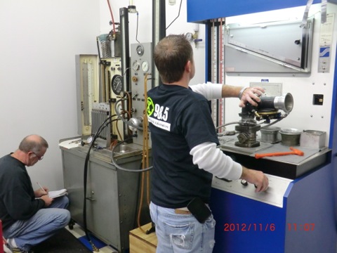
The guys at Performance are terrific. Kyle loves to talk to customers and let them observe the testing process and explain what is going on with the tests and the results. Instant feedback on the problem and an opportunity to learn about my equipment. I LIKE it!
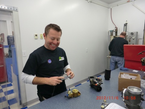
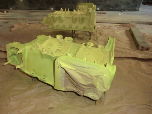
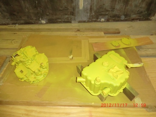
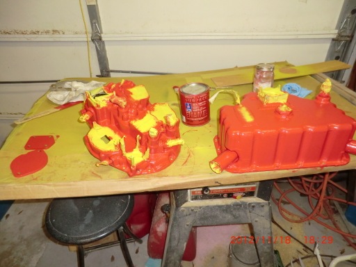
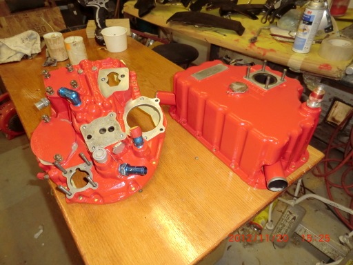
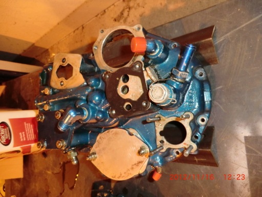
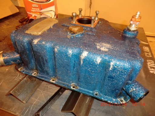
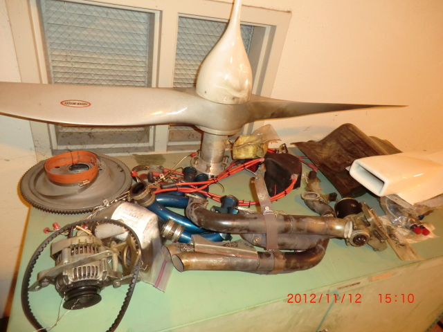
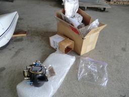
The shop always takes lots of pictures (before/after) of the equipment to ensure there is no question on the material condition of the items.
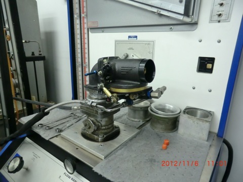
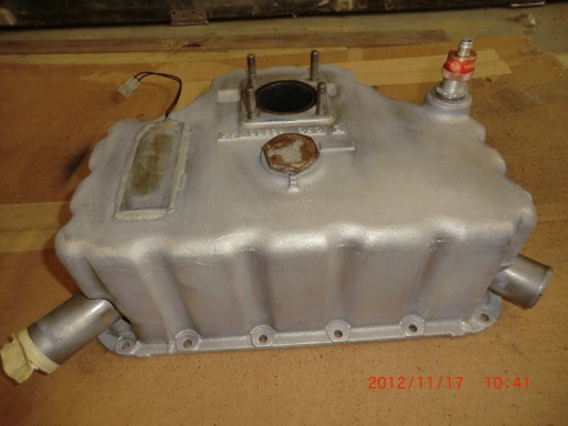
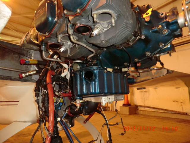
Here is the fuel servo mounted in the air flow box to test fuel output at different power levels.
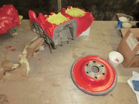
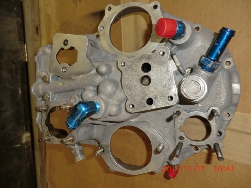
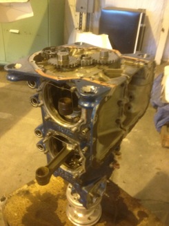
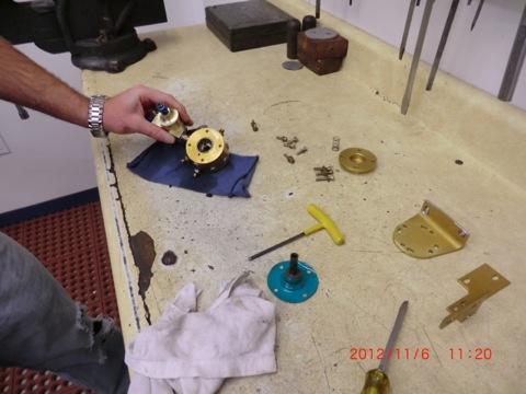
Hum, the fuel servo passed all it’s tests perfectly, but the little fuel divider “the spider” failed.
When Kyle took the flow divider apart, he found the filter to be clogged and needed to be rebuilt. The little filter in the divider is what is restricting the fuel to the engine not allowing fuel flow at the normal max fuel flow of 12-13 gph . Currently, I could only get about 8 gph and can not get the rpm above 2480 rpm. During my flight on friday, I could only get 7 gph which is why I had to land in a hurry. NO fuel, NO power!
After talking with Kyle about my options and finding out that the normal service life of the unit is 10 years before overhaul (mine is 8 years old) the decision was made to just do a complete overhaul/rebuild of the equipment. It would have been due in another 2 years anyway. An overhaul is the most prudent and safest coarse of action.
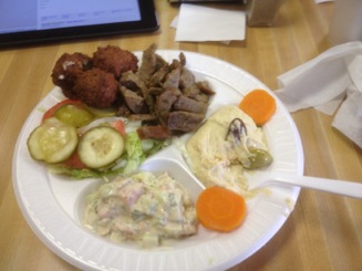
I left Airflow at 12:30 pm, drove about 25 miles to Greenville for lunch at my favorite restaurant in SC. The Pita House. They make the best Mediterranean food in SC.

Mediterranean plate with gyro. It was SO good I order the same dinner to go. I’ll make some humus and have it dinner tonight!
After another 200 mile drive home, I passed my voting place at 4:30 pm and there NO freaking line at all. None! It would have taken me 5 minutes to vote. Next time I will wait until later in the day to vote when everyone is at work.
I won’t get my fuel servo and divider back until late next week, so I can now work on the house instead of spending my days at the airport. Yahoo!