Nov 28 2009

Wiring has begun

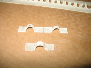
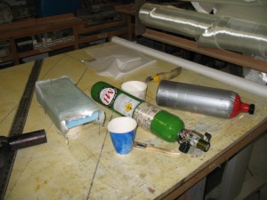
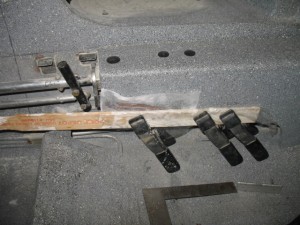
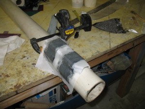
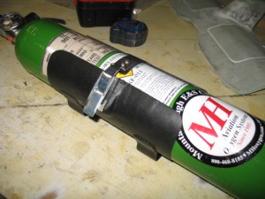
This has not been a busy of a week for me.  I was sick the first part of the week and with Thanksgiving thrown in, the work on the plane slowed a bit.  I was able to complete a few items.  I built a O2 bottle support which came out very nice.  The bottle is the same size as a 4″ PVC pipe which I used as a form to lay the glass on. 
Attaching the support for the closure clasp.
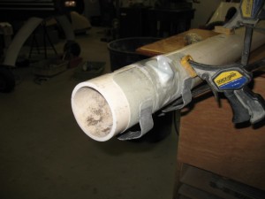
Finished.  Painted flat black.
Insturment Panel

I have changed the plan a bit and now want a carbon instrument panel.  Quite a few hours this week was spent finalizing and rechecking the Acad drawing so it can be cut out on a CNC machine in LA.  I should have a test panel in a week or so.  After I finish installing the supports and lettering it,  the panel will go back LA for clear coating and polishing. 

WIRING

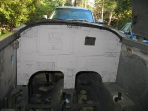
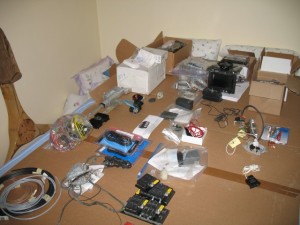
I also started working on the wiring system.  I have been avoiding the wiring just becauseI know how much work it is truely going to be.  Many, MANY hours sitting at the computer drawing and documenting the wiring harness.  After installation, there will be many hours of correction the drawing for final printing.   I laid out all the major electrical components on my spare bed and looking at all the wiring ahead is daunting!
IMG_3842   

The wiring diagrams are absolutely CRITICAL to long term maintenance of the plane and they need to be as complete and clear as possible.   After flying these planes for years, I find most of the maintenanceissues in the future will mainly be wiring problem.  Fixing a screw, bushing or engine component is quick and easy.  Finding out why a light or radio stops working is really tough and almost impossible without a well documented wiring schematic.    The type of connectors, switches, plugs, type of crimper used, wire, etc should be of the highest quality possible, because it will bite you in the butt if  you dont pay really close attending to this critical aspect of the plane.    Of all the work I am doing on the plane, I approach this area with the greatest concern and closest attention to detail possible.    This is why it takes so much time and effort.  I spent 3 hrs yesterday working on just 4 pages of wiring and I am still not done.    I will probably have 30 or 40 drawings.   

Some people approach the electrical draw from the aspect that you should put everything in an area on one page.  An example is the power system should show all components and where they all go (charging, starting, lights, lines to the radios, etc).  This is great for wiring the plane, but doesn’t help as much when you are trouble shooting a sub area of the larger system.  Lets say you are only working on the alternator part of this system.  

I like drawing the areas out in sub systems.   The alternator system is drawn separately from the starting system or the ignition system.   In the future when you are trouble shooting  problems with the charging system, it is MUCH easier to look at just the system of interest and visually see what is going on.  You dont have to separate it from a larger drawing with lots of other stuff on it.  It makes wiring the plane more of a pain but is much easier to trace wires.   

Anyone can wire a plane… it is not rocket science and is fairly easy to do.  Run a wire from A to B and you are done. Easy.  I have seen so may planes (certified and experimental) where if you ask the owner for a wiring diagram, you’ll get a blank stare.    I have seen very few few wiring diagrams and they were by obsessive compulsive engineer types who really knew the value of having one.   Most builders just wing it.    I had to rewire my plane because of a crappy wiring job and no documentation and did a fair job drawing out the wiring on Tweety.  On this plane, it will be the mother of documentation because I plan to reuse most of it on my cozy 4 (Bubba) so it is worth the extra effort.    Beside, I want to do it right for myself .

Wire Zip Loops Ties

One thing which has always bothered me was how do you attach the wire bundles to the plane.  In my plane I used click bonds with Adel clamps which are heavy and awkward to use.  I wanted something easier to install and more versatile.    So I made up some attachment point I call bow-ties.

First I layed some glass over some small diameter rods.
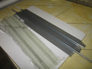
After slotting the glass layup (I used a radial arm saw), you can cut them up into individual loops or as strip and flox them to the surface of the fuselage.  A zip tie to hold the wire bundle to the bow tie and you are done.  I weighed a single zip loop and it works out to .5 grams each.    What I like about it is if you wish to have a number of separate wire bundles (my favorite choice) you can cut a strip of zip loop ties and flox them down as a group.  Then the wire bundles are equally spaced out along the wire run.
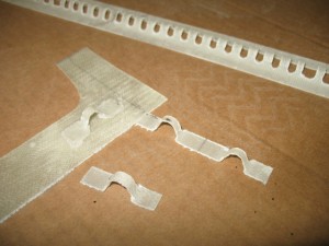
I think may make another strip of ties which will improve my original design.    The first set used a rod as the form and was a very easy way to make a strip of bow ties, but the top of the ties is rounded and a bit taller than I want.  I plan to make a gig which will be squared on the top (3/16″) about 1/4″ high and use 2 layers of carbon.  It will hold the zip ties better and I have plenty of scrap materials around to try it out.
Nov 19 2009

Panels are done!

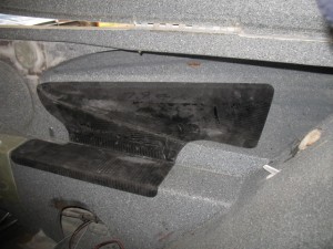
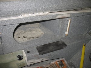
I completed a quite a few items the last couple of days….  the instrument panel cover, the passenger foot rest/storage area, and the panels for the arm rests.

After presenting Pat with 8 different options, he chose this shape for the pilot arm rest area.  More cushion than needed but it is for the overall effect he wants to achieve with the plane.

Finished panel weight 8 oz. 

Stbd side.

Back seat.

Today work was started on making a O2 bottle support bracket and installing the fire control system bottle.

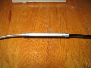
This was an AWWWwww SHIT today.  The cable which activates the fire suppression system is too short so it is necessary to make some sort of adaptor to lengthen the cable.   A simple tube with bushing seemed the way to go.   Good….done…   Well when I looked at routing the new cable in the plane, I f0und you can not use this method as it will not fit through a hole in the instrument panel.  I need to have a way of attaching/detaching the extention cable from the main cable.   Tomorrow, I’ll remove it and start again. I personally would use halon for fires not foam….

Nov 16 2009

Arm rests

Work started back on the plane.   I finished the cover for the belly board motor.    It came out nice.  Today it was glassed to the foot rest.

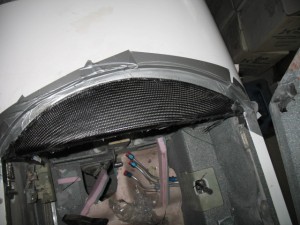
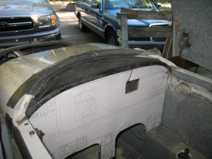
The instument cover actually came out better than I expected.  The carbon graphite is incredibly stiff and it made a really nice cover.  I like the rounded look of the carbon weave. 

The cover is going to be clear coated which will make the carbon really stand out.  It will end up looking great!

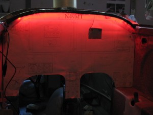
I tried lighting it with the LED strip light which fits under the lip of the panel.   The lighting is nice and even.

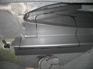
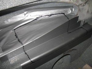
This is the plan for the arm rest.  Typically I like to rest my arms in the strake opening.  The sharp edge of the stake is very uncomfortable on the elbow, and it occurred to me to pad not only the flat surface but some of the strake area too.    After glassing the panel it will be covered and RTV to the plane.   I use RTV in my plane to hold my arm rests which has worked out very well over the years. 

Stbd side.

Port side


Nov 11 2009

Instrument panel cover

Today was spent working on interior panels again….  Pat wants a cover for the belly board electric motor.  I’ll show pictures of that tomorrow.  The eye brow cover for the instrument panel was also worked on.  It turns out it is actually quite complex to make due to the curvature of the canopy and the desire for a lip to hide the LED lighting.   

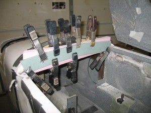
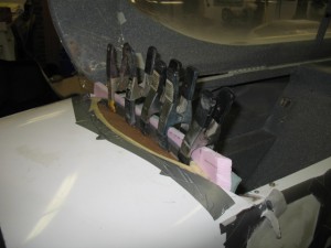
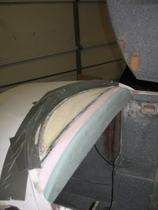
First, foam was glued to the face of the instrument panel.  Two thicknesses of foam was used to get the necessary thickness and the green foam allows the radius to be easily judged for consistency.


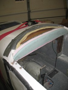
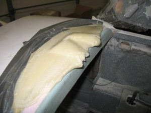
Some cardboard was placed forward of the panel and expanding foam was poured into this area and the canopy was closed.  After the foam expands and sets a perfect image of the inside of the canopy will be formed.  it will be easy to then sand the foam to a pleasing shape and glass with carbon graphite.

After using pour foam and closing the canopy, I had an exact impression of the canopy which could be sanded to make the support form of the instrument cover.

IMG_3768

After sanding to shape.

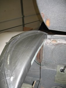
Taped, waxed and ready for glassing.

Nov 09 2009

Extra Storage Area

I was out of town this weekend.  Flew up to PA to visit Mom and fix her TIVO.  The trip was GREAT and my average speed was about 190 mph.  Cant beat that!  The OAT got down to 27 F at 8000 ft and Tweety’s oil heat system worked great!   The toes got just a little cold, but I wasnt even wearing a jacket, just a light shirt.   The main problem is getting enough air to the nose of the plane from the heat core installed under the back seat.  I will probably rip out the SCAT tubing I used (hate the stuff) and make some fiberglass tubes to reduce the head loss in the system like in pPod. 

With pPods nose installed oil cooler and tight sealing of the nose area to reduce drafts, the plane should easily be good down to 10 F or less.  I have never flown below 15 F so we should be good for just about any flying.  Since the plane will be delivered this winter, I’ll have a chance to really test it out.

Today was spent mostly preparing for glassing.  I didn’t like the match up of lines on the STBD panel from the old to the new, so I added some glass to the existing installed arm rest.

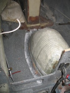
Also glassed was the insulated cover cover for the wheel well.  Insulating the wheel well is very important to keep the heat in during the winter.  You can actually feel the heat being sucked out of you when you are straddling the WW on a very cold flight.  The WW is only 3 layers of glass so it does almost nothing to keep the heat where it belongs… in the plane.

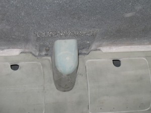
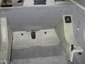
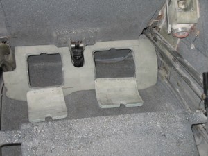
The openings for the rear foot rest were cut and springs installed to let them ‘snap’ shut.  I tried sitting in the plane the the foot support is very good.   I really like the extra storage and may add them to Tweety.

There is actually quite a lot of storage space in them.  I plan to put the ELT in the smaller side.  I want a cover for the actuator so it cant be seen. 

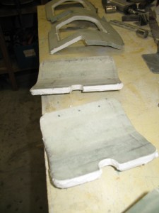
All edges of the doors were filled with micro.  I think is a very easy step and makes the panels look much better.  It also keeps the foam on the panels from ripping off the glass over the years of abuse and allows for a slight rounding of the edges to soften them a bit.   A very important step in my book.

Nov 02 2009

Drip Rails part 3

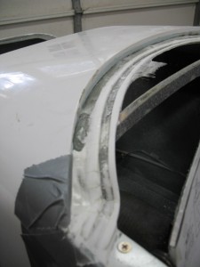
Today was spent entirely spent working on the drip rails.  After sanding, the back one came out beautifully.  The front one has issues.    As it was being sanded and shaped, I wanted to see  if the instrument panel would still properly fit.

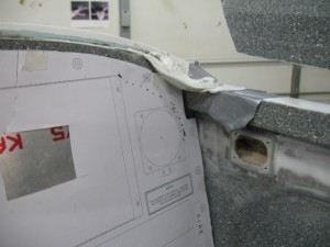
SHIT!  The funky shape of the canopy caused the seal area to dip way down which now interferes with the installation of the instrument panel.  I would have to trim and cut off the corners of the instrument panel which is totally unacceptable.   Doing so would work but it would ruin the look of the panel.   I had to step back, re-evaluate the whole thing and come up with a different game plan.  The drip rail needs to be installed no further than the pilot side of F-22 to achieve the right look.

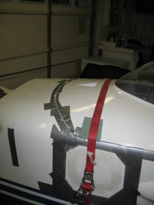
A second seal was placed in micro, and the canopy closed.  Tomorrow, I’ll see how it looks and how hard it is to dig the seal out of the micro.   The thing I really like about fiber-glassing, is I could always cut everything out and start over again if necessary.   I hope that option is not necessary.   The strap around the plane holds the canopy tightly closed while the micro is curing.