Category: Electrical

Aug 17 2010

Wiring started

Today was mainly spent ordering electrical supplies.  I want to make the instrument panel completely removable with cannon connectors so it can wired and operated on the bench.  The connectors are cheap, but the dam pins are very expensive.  I think that is how they really make their money…. little machined pins.

I have started to pull wires as I am waiting on the oil pan to be machined flat.  I cant put it on the engine just yet because the welding process warped it.  It rained all day in Charleston, so I couldn’t paint the engine mount either.

The headrest area behind the passenger is going to be very busy with wiring and instrumentation.  It will all be covered by a trim piece and a headrest.

The wiring from the engine monitor has 50 wires connected to it.  Each one has to be identified labeled and tested, then the drawings needs to be reviewed and corrected.  Tedious, but very necessary for future maintenance.   Actually I kind of think it is a bit of fun.  Sort of like doing a puzzle, sort of like doing artistry because it also has to look good when you are done too.

Jun 21 2010

ADS-B antenna

Today the ADS-B antenna installation was finalized.  Installation requires two things…. a ground plane (done) and somehow attaching the antenna to the fuselage.  It finally occurred to me, I didnt need to dish out the 1″ thick interior foam to fit the 1/2″ long antenna studs, I just extended the studs with some threaded brass bushing made on the lath.  This made installation MUCH easier as I now can easily access the nuts without cutting up the interior.

I talked to the manufacture of the CuPro-CoteTM paint.  He said others have used it for ground planes and it works great.  If you plan to use it, paint it in THIN layers since excess acrylic binder (if you paint it thick) actually reduced the conductivity.

Five patchs of copper tape was cut in a sort of “E” so there would be more edge surface contact area for the paint and attached to the bottom.  

Then the entire surface was given a second coat with part of the tap left unpainted so a wire could be soldered to the tab the then covered with a patch of BID for protection.  I don’t know if I need the extra wire connecting the sections as the resistance of the surface after a second coat of paint from the hell hole to the nose (about 7 ft”) was only 8 ohms. 

Jun 20 2010

Ground Plane

Ppod needed some additional “ground planes” which are used for making the antennas work properly.  Some antennas need large ground planes to work such as the transponder and ADS-b antennas.  Since I am adding new antenna (the ADS-B) and there is not enough much room in the plane for the size recommended.  In my plane I had to compromise with smaller ground planes or really odd shaped ones (such as for my lightening detector).  A few years ago, I found some electrically conductive paint which was used in my plane for reducing electrical noise (as shielding).  Ken Miller apparently used a conductive paint successfully for the transponder antenna he installed and since ATC reported no problems picking up the transponder signal, it was decided to just make the area much bigger. 

The entire bottom of the passenger area was painted with this stuff.   After drying,  I tested the resistance of the paint and found it amazingly conductive.  It reads 17 ohms across the fuselage (about 18″).  When tested it with a 12v source, it did not loose .01 volts from front to back of the plane!   I also plan to attach some small copper tape (about 1/2″ sq) to the one side every 12″ and solder a wire on each tab to ground.    It will be interesting to see how this new system works in flight with ATC. 

I hope this works well I can use this technique in future planes!  **NOTE: I used this technique to “enlarge” the ground plane in my LongEZ.  I can now report NO more problems with ATC picking up my transponder.  It is working better than ever!

The fire system bottle was installed today.   I replaced the 2 ea stock bottle holders (47 g ea) with a riveted hose (6 gm) hose clamp with a finger actuator.  You will have to stick your arm way up the spar to tighten the wing bolt and was concerned about interference with the stock clamps.  The hose clamp can swivel out of the way, and overall I saved 96g (3 oz) with the mod.

The additional cable installation for the fire system was micro’d so it will be less noticable when finsished out.

Today we had a very strong thunderstorm after I went flying.  It was easy to see on the XM weather in the plane and my lightening detector was showed significant activity.  This evening, the club manager called and I found out part of the roof of the hanger had blown off.  After checking my plane over, all is well.  Base maintenance should be fixing in the next few days.

Updated pictures of the Boeing 787 Dreamline plant.  They are making amazing progress on it.  The contractor has now started on moving a 2 mile road 500 feet to the south to enlarge the manufacturing site.

The Dreamlifter

Jun 15 2010

Windows CRASH

This afternoon while emailing DURING A THUNDERSTORM, my computer crashed….  Big time crashed.    I know,  you have always been told turn off all your electrical stuff during a storm.  I THOUGHT I was protected with a UPS and an isolated system, but no, a big crack of lightening,  computer crashed and next thing I know there was the “Hard disk not found” during boot up.  Yikes! 

As recommended I had made a “Recovery Disk” (imagine that)  when I installed the operating system and as annoying as the daily backup is (slowing down the computer) for some reason, I had let it run to completion this morning.   I booted up on the recovery disk, had to do a complete re-image of the computer “C” hard drive (from this morning’s back up) and wala! the computer is working perfectly again.   I keep all my data on the “D” drive (a second drive)  so I didnt lose a single file.   Windows 7 is terrific in my book!   Now I just need to turn off my computer during the next storm.

I had the fuel caps engraved.  Actually they look very cool.  I’ll paint the lettering a suitable color when the plane is painted the plane in Calif.    Polished up and lettered I am sure they will look great!


Disassembly of the plane to prepare it for painting continued today.  I have a huge pile of parts now.  I want to weigh everything added to the plane (such as the heating system) to see how much my work affected the weight of the plane.

The HID landing light installation gave me a bit of trouble. At first, I didnt think it could be installed.  The HID bulb is much taller and a little larger in diameter by 0.015″.  Doesn’t seem like much but the bulb would not sit flush to the bracket . 

Careful, extensive filing and bending of the aft brace bracket was required to get it installed.     The HID light is incredibly bright and requires much less power than the standard 150 watt ligth that was installed. 

Installation of the Halon fire suppression system was stared.  If a fire is sensed in the engine compartment (there will be an alarm on the EFIS),  the pilot can pull a handle on the dash which will flood the engine compartment with halon and quickly put out any potential fire.

May 26 2010

Antenna Brackets

Today was spent mounting more parts for the electrical system.  The XM antenna was mounted in the nose area so Pat can easily remove it IF he want to use XM with his portable GPS in another airplane.   There will be connection plug near the antenna so the wiring in the plane will not be disturbed.

The three GPS antennas were also mounted in the plane as well as the starting solenoid.

I also fabricated the elevator trim spring.  I’ll check out the flexibility of it after curing and if necessary add more glass to stiffen it up.

Next will be finding a place and installing  an external ADS-B  antenna (the last one!)

May 25 2010

Electrical Started

Work has been started on installing the components of the electrical system.  The area behind the passenger headrest is incredibly tight with components.  I wanted to install as much as possible in this area to make the electrical parts easily accessible and to remove them from heat of  the engine compartment.   When I get to actually wiring the plane, firewall penetration bushing will be machined out of fiberglass rod to protect the wires allow the installation of fire stop around the wires.

The forward fuse panel will be inststalled under the thigh rest.  These fuses should never blow (clock power) so access would be rarely required.

May 03 2010

Epoxy coating

Today was spent on epoxy coating the canard, elevators and micro repairs on the fuselage.  I put 5 coat of west on the uppers surfaces.  It is amazing how well it fills pinholes and scratches.  Tomorrow the bottom surfaces will be coated.    After the epoxy hardens, I’ll be able to sand the surfaces and prime them. 

Fuselage repairs have been coated too.

Between the epoxy applications the mounting of the electrics has begun.  Before the plane is wired, locations most of the equipment  needs to be found.   Clearances checked so you can get the components out if it needs to be serviced (when the plane is fully assembled).    The problem with a LongEZis  how tight everything is.   Without the instrument panel (with the radios installed), it is becoming hard for me to imagine where all the stuff is going to go.   This plane is PACKED with goodies and space is really tight.    One has to imagine electrical interferences (high power lines, transmitter cables, magnetic interferences, ground planes, etc) so everything will work without “cross talk” or noise in the audio system.  What a PITA.

Apr 26 2010

Choop not doing so well…

Today was a relatively fun day, but somewhat short one.  I had a slow start due to a slight infection (I hope it is not from Chomp)…

I decided to move the BOTTOM VOR antenna connection from where I just installed it last week.    I thought it was not the optimal postion for easy access and thought there could be a better place for it.    I could have easily left it in that location, but since I was installing TOP #2 VOR connector on the front of the canard cover, why not move #1.    It only take a few moments to put in, and even less to take out.  Worked out great!  

Former location

New location:

Glassed in.   Now when you install the canard, the BNC’s are protected, easily visible and easy to connect.

The Trio Pro pitch control system is installed with all the hardware.   My installation instructions I published a few years ago for the community still work well.  I will have to make a few updates to take into account a changes on the rotary arm and servo tab length.   Wiring needed.

The closure of the hatch door is complete and sanded.  Ready for epoxy sealing.   Need to complete the installation of the canopy closure system (tomorrow or Wed).

The Grand Rapids Horizon HX EFIS electronic sensor module (dual AHRS).  This box contains he main instrumentation sensors for the glass panel.   Wiring and tubing needed.

I am taking Chomp to the doctors tomorrow.  I think he may have had too much alcohol to drink.  He just doenst seem to have much energy lately.

Apr 09 2010

Headset Bushings

Today was a short day.  I had to make some mod’s on the laminater (for lettering) per Tech Support of Pulsar.  It should work a little better now.   

I made the new passenger comm panel (the original was sized wrong).    I checked the panel’s resistance (made of carbon fiber) and sure enough, it is VERY conductive which is a problem for the audio system.  Since the headset jacks are grounded, it means there is a real possibly of a ground loop from the mic to the headset ground via the carbon.  

This is the same issue which plauges an alum plane.  Many pilots find there is a bit of noise (whine, strobes, etc) in their headset caused by ground loops.     As owners started upgrading to carbon and aluminum panels few pay attention to the ground loop issue and are surprised to find their new system has more noise than their old setup.   The owner did not take into account the jacks which were mounted in electrically isolating fiberglass, now are mounted in carbon or alum and are creating a ground loop and noise.

In order to prevent comm noise,  a bushing and washer was machined out of delron to electrically isolate the mic and headset jacks from the carbon to eliminate the ground loop.

The new panel and bushings.   I’ll letter it tomorrow.  Now that I know what I am doing with the lettering kit, it should only take 20 min or so.

Nov 28 2009

Wiring has begun

This has not been a busy of a week for me.  I was sick the first part of the week and with Thanksgiving thrown in, the work on the plane slowed a bit.  I was able to complete a few items.  I built a O2 bottle support which came out very nice.  The bottle is the same size as a 4″ PVC pipe which I used as a form to lay the glass on. 

Attaching the support for the closure clasp.

Finished.  Painted flat black.

Insturment Panel

I have changed the plan a bit and now want a carbon instrument panel.  Quite a few hours this week was spent finalizing and rechecking the Acad drawing so it can be cut out on a CNC machine in LA.  I should have a test panel in a week or so.  After I finish installing the supports and lettering it,  the panel will go back LA for clear coating and polishing. 

WIRING

I also started working on the wiring system.  I have been avoiding the wiring just becauseI know how much work it is truely going to be.  Many, MANY hours sitting at the computer drawing and documenting the wiring harness.  After installation, there will be many hours of correction the drawing for final printing.   I laid out all the major electrical components on my spare bed and looking at all the wiring ahead is daunting!

IMG_3842   

The wiring diagrams are absolutely CRITICAL to long term maintenance of the plane and they need to be as complete and clear as possible.   After flying these planes for years, I find most of the maintenanceissues in the future will mainly be wiring problem.  Fixing a screw, bushing or engine component is quick and easy.  Finding out why a light or radio stops working is really tough and almost impossible without a well documented wiring schematic.    The type of connectors, switches, plugs, type of crimper used, wire, etc should be of the highest quality possible, because it will bite you in the butt if  you dont pay really close attending to this critical aspect of the plane.    Of all the work I am doing on the plane, I approach this area with the greatest concern and closest attention to detail possible.    This is why it takes so much time and effort.  I spent 3 hrs yesterday working on just 4 pages of wiring and I am still not done.    I will probably have 30 or 40 drawings.   

Some people approach the electrical draw from the aspect that you should put everything in an area on one page.  An example is the power system should show all components and where they all go (charging, starting, lights, lines to the radios, etc).  This is great for wiring the plane, but doesn’t help as much when you are trouble shooting a sub area of the larger system.  Lets say you are only working on the alternator part of this system.  

I like drawing the areas out in sub systems.   The alternator system is drawn separately from the starting system or the ignition system.   In the future when you are trouble shooting  problems with the charging system, it is MUCH easier to look at just the system of interest and visually see what is going on.  You dont have to separate it from a larger drawing with lots of other stuff on it.  It makes wiring the plane more of a pain but is much easier to trace wires.   

Anyone can wire a plane… it is not rocket science and is fairly easy to do.  Run a wire from A to B and you are done. Easy.  I have seen so may planes (certified and experimental) where if you ask the owner for a wiring diagram, you’ll get a blank stare.    I have seen very few few wiring diagrams and they were by obsessive compulsive engineer types who really knew the value of having one.   Most builders just wing it.    I had to rewire my plane because of a crappy wiring job and no documentation and did a fair job drawing out the wiring on Tweety.  On this plane, it will be the mother of documentation because I plan to reuse most of it on my cozy 4 (Bubba) so it is worth the extra effort.    Beside, I want to do it right for myself .

Wire Zip Loops Ties

One thing which has always bothered me was how do you attach the wire bundles to the plane.  In my plane I used click bonds with Adel clamps which are heavy and awkward to use.  I wanted something easier to install and more versatile.    So I made up some attachment point I call bow-ties.

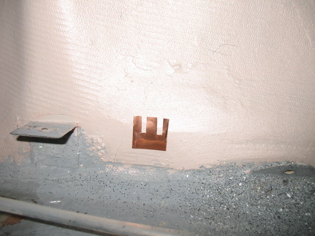
First I layed some glass over some small diameter rods.

After slotting the glass layup (I used a radial arm saw), you can cut them up into individual loops or as strip and flox them to the surface of the fuselage.  A zip tie to hold the wire bundle to the bow tie and you are done.  I weighed a single zip loop and it works out to .5 grams each.    What I like about it is if you wish to have a number of separate wire bundles (my favorite choice) you can cut a strip of zip loop ties and flox them down as a group.  Then the wire bundles are equally spaced out along the wire run.

I think may make another strip of ties which will improve my original design.    The first set used a rod as the form and was a very easy way to make a strip of bow ties, but the top of the ties is rounded and a bit taller than I want.  I plan to make a gig which will be squared on the top (3/16″) about 1/4″ high and use 2 layers of carbon.  It will hold the zip ties better and I have plenty of scrap materials around to try it out.