Category: LongEZ Upgrade

Nov 08 2010

An instrument panel is born

I decided to take a few pictures of the current work as I am going to take a couple of days away from the work to get a some chores done.  Sort of a working vacation.

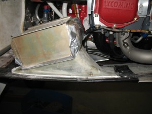
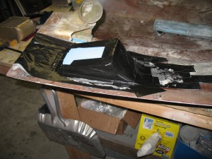
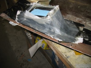
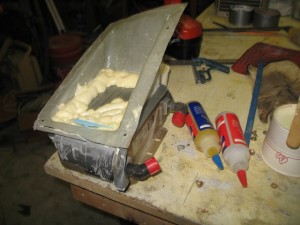
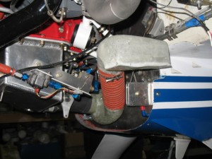
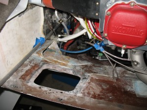
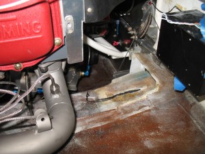
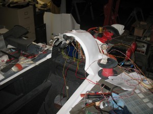
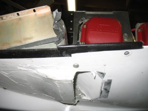
Here is the shape of the outlet duct I came up with.  It is a much smaller outlet than original and compresses the air prior to injection in the airstream.  I wanted a slight kick out to create a low pressure area just in front of the outlet (somewhat like my plane which I know works well.  When I start flying the bird, I’ll record some data reading to see just how well it compares to my plane.

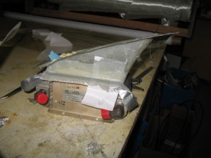
the oil cooler was tilted 25 deg from orginal.  Te final effort is creating the inlet duct.   Some sanding and it is ready for paint!

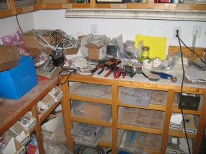
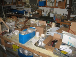
I made the decision to organized all my electrical stuff.  It is much more efficient to have everything inventoried, organized and easily assessible to speed up electrical work.   I was getting frustrated looking for stuff asit was slowing my progress down.

A table full of … stuff….    Now I have to sort through all this stuff and get it organized.   This will take HOURS (but time well spent ).

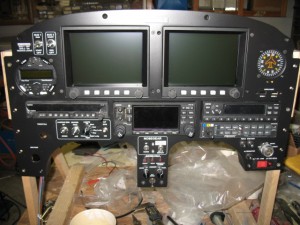
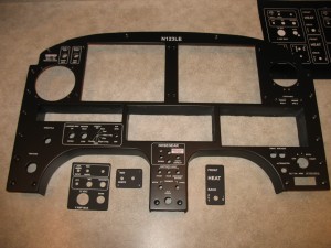
I also wanted to populate the instrument panel to see how it would look and it is freaking beautiful.  This picture doesn’t even begin to do it justice.  It it going to look fabulous when installed in the plane!

I am extremely pleased with the result.
Nov 07 2010

Almost a Gear Up…..

Today was a great day.  I drove up to Summerville this morning to look at a 1995 Mercedes diesel.  It turned out to be a bust…  I then flew over to Mt Pleasant to meet up with Mike to fly together.  

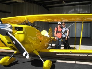
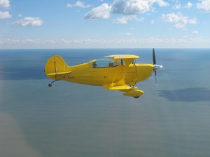
He has a beautify acrobatic plane a IO-360 (180 hp) christian eagle.   Mike is taking his wife up for her fist flight. 

I bet she was happy when he did a quick barrow roll!

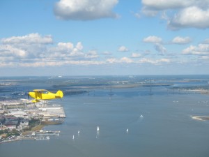
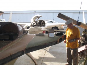
This is a great shot over Charleston with the new bridge in the background.  The crazy thing he kept asking me to slow down.    Mike had his plane firewalled at 130 kts, so we slowed down to 125 kts (2700 rpm) and  I was only turning 1900 rpm.    When I left him, I firewalled my plane and quickly pulled away from him.  I never felt so fast!

While I was landing, I noticed the lock gear down light was not lite and I could not cycle the gear down properly (about 1/8 turn from full down).   This seemed strange to me and  I felt the over-center device hadn’t engaged so I called the tower to let them know I had a gear warning light.   Sure enough when I touched down, the nose started to collapse.   Sort of progressively dropping instead of a quick drop, BANG.    I was almost stopped with I hit the ground.   The plane was moved off the runway, I lowered the gear (this time it locked) and taxied back to the hangar.

Minutes later the towered called me.  Within 30 minutes the S.C Flight Standards Office called for an update.  If only the rest of the federal government worked as well as the FAA.  

I told the FAA there was no problems, the plane wasn’t damaged, (it wasn’t) and everything was ok (it was) then immediately started tearing into the nose to find what what going on.  I was lucky this time, I only ground about 1/4″ off the nose bumper!

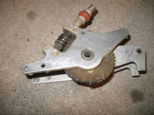
I removed the nose gear assembly and found the gear had stripped.  It was tuned 180 degrees (just flipped over) and it was as good as new.  Reassembled the plane, test all and decided it was an anomaly and watch for any warning signs in the future.    Another new experience to learn from.

One good thing about this event is that I now think I can install a electric nose lift in the plane.    I always thought there was not enough clearence in this area, but after disassembling everything, I now believe it can be done.

After fixing the plane, I stopped by to see a bunch of my retired navy officer friends at the yearly RINK roast at the Elks Club.  It was great seeing some of my old buddy’s.

Overall, quite a busy and exciting day!

Nov 01 2010

Boooo

I have to take a necessary break from the wiring to wrap up a few last items.  The oil cooling, the 406 ELT and final installation of the fire suppression system.   

I didnt really like the straight down (original plans) type oil cooler installation.  There is no expansion of the inlet air (increases pressure) or contraction of the air (pressure recovery) so I decided to tilt the oil cooler 25 deg to allow a smoother flow of air into and out of the cooler.    I also replace the cooler with a more efficient Stewart Warner.

First step is establishing a base plate and shape of the outlet duct.

Next is to glass it.

I now have to build flanges on the duct to bolt the oil cooler on.

The flanges have been glassed.    Tomorrow, the cowl will be glassed for the outlet air flow after which the inlet duct will be fabricated.

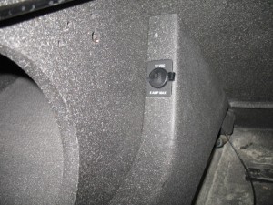
In between all this, I installed the back seat electric panels.  The came out exactly as planned.  Very cool looking!

Both panels have a 12 vdc constant on plugs (so you can charge your phone at an airshow).

Boo..

Oct 28 2010

Wind Generator Dedication

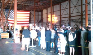
Today was interesting.   At lunch I attended the official dedication of the soon to be built national wind generator gear testing facility which will be run by Clemson University.   Development of the facility is being funded through a $45 million grant from the U.S. Department of Energy and an additional $53 million in private donations. Within days of announcing plans for a testing facility last November, IMO Group, a German company that makes wind turbine parts, announced it was opening a plant in North Charleston that would create 190 jobs.

It is  predicted thousands more jobs may be just around the corner as the Institutes 100-plus acre campus on the site of the former Charleston Navy Base grows.  When completed the site will be able to test the largest of  gear trains for off shore wind generators to failure.    One speaker said this is one of the most important sites for wind energy research and development in the country.  Plenty of pomp and circumstance for the crowd, but where is the food???

We were addressed by our senators, congress men and the city mayor.     The speeches were short and to the point.  Just how I like them.   Hum… food? It is lunch time.

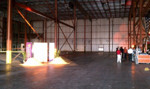
This picture turned out interesting.  The piles of orange dyed sand (Clemson colors) seemed to glow like pots of gold.  Since the building is already built, officials will dig into the sand piles with shovels for the smiling money shot….

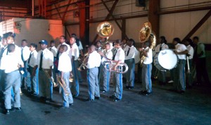
A local high school or possibly elementary school (maybe kindergarten?) band provided the dedication music…. all I can say is they tried hard.    Where is the feaking food???  I’m hungry.

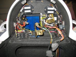
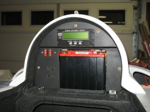
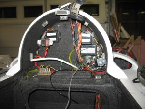
The headrest area is done.  I now have the EIS, aft battery, fuel level indicators, power distribution (aft), electronic ignition’s and starting system finished.   This is how it looks before the beauty panel.

This is with the cover panel in place.  You  will never have to get to the electronics behind the panel unless a part fails.  I’ll letter the panel with the obligatory warnings, fuse sizes, etc to dress it up a bit.

The coils for the Lightspeed ignition are done.

BTW:  There WAS NO FOOD at the$98 million dollar dedication.  Cheap bastards……

Guess I’ll have to buy my own lunch.

Oct 26 2010

Waste Oil Mess / panel update

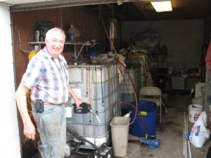
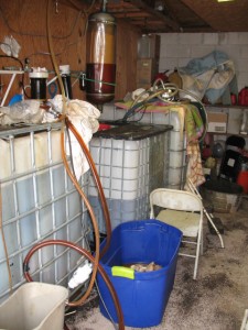
Drove up to Summerville to get some waste oil for my car and Gerhart and I and a bunch of problems with the filter system

We had one bag rupture in the filter housing.  I guess it just got too plugged up and the pressure got to it.  After we finally got it out (in the blue tub), we installed a fresh filter and it came unhooked and plugged the system up.  Lessons learned…. put a pressure gauge on the discharge of the pump (to monitor the health of the bag) and install the new bags differently than what I did this time.

In both cases, it is easily fixed.

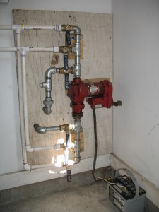
I FINALLY talked Gerhart into letting me install a proper piping system similar to the one I have in my shop for his tanks and filter.  It drives me crazy to have such a mess of hoses and loose pumps that trying to make things work when it can be properly engineered so easily.  On Saturday, I’ll make up the manifolds and install everything next week.  

I also flew from Charleston to Mt Pleasant to visit Jack Wilhelmson to help him install my fuel probes in the new cozy 4 he is building.    Although it is only about 40 min by car, I can fly there in 7 minutes from the hangar (plus 10 minutes to the house).    17 minue trip time is great plus I got to fly today!

The fuel  probes went in very easily with no problems.  It only took about 10 minutes /probe.  It is SOOOooo much easier to install them on a new build than on an existing plane which (which is fairly easy to do anyway).

No work done on my plane today….  bummer.  Tomorrow I’ll really hit it again on the wiring.

UHOOOOO…  Quick update

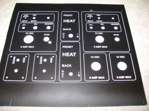
UPS delivered the instrument panel tonight.

After months of false starts and many tries I am positive this panel has turned out to be the labor intensive and totally frustrating EZ instrument panels ever made.   I must have spent at least 40 hr just lettering it, after which it was sent to CA for clear coating.  Everything was sanded off.    It was then sent to a avionics shop in Chino, Ca for printing.  They had it for months and it ended being sent back to me completely untouched.  

I then spent numerous hours custom fitting (back setting) the radios for a differnt type of look and fitting it to the plane (to make dam sure it would fit as expected this time) before being sent to Aerotronics in Billings MT for lettering.  

Aerotronics did a great job and it looks FANTASTIC!!  I cant wait to see it populated with instruments in the plane.

Extra side panels in case I need them.

Oct 25 2010

EIS done

The engine information system is done!  Ya!  To go from such a mess of wires to this is great.   Now begins the fun of connecting the battery and fuse to the loads.

Black sleveing was put on the majority of the wires where possible.

Looking good now. 

Oct 18 2010

CHT wiring trick

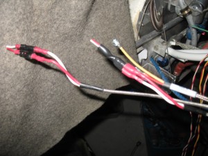
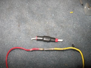
There is not a lot to show you when wiring a plane.  Maybe a jumbo of wire, then everything neatly organized.    Here is a little trick I have been using for installation of CHT’s and EGT’s.

You have to connect the probes up to the readout equipment.  Normally, one uses ring connectors or 1/4″ push on connects as most do.  I think they are bulky and unnecessary. 


What I like to do is to do an inline splice with a sub-D barrow pins.  Just put pins on the wires, put heat shrink over them to hold them together and you are done.  After heat shrinking the junction, I always heat shrink the two wires together as a pair.  It make a great connection, there is very low voltage through the joint and since the sub-D pins are gold they will last the life of the plane. 

These joints makes the wiring  job not only look better, but are very compact.

The stbd side of the engine is done.

Oct 16 2010

Fuel Servo Inlet Duct

The last few days were spent working on the fuel servo inlet duct.  I wanted to use the armpit scoop on the right side of the cowl instead of cutting through the firewall into the hell hole.

After visualizing what was needed the part had to be carved out of foam.  First I had to carve the part out of foam and glassed. 

After a few hour under a vacuum, the part was read to be revealed.

Here it is with the foam still on the inside. 

Tony stopped by again to check out the work.  He thought it all looked “smashing” and “very clean”. 

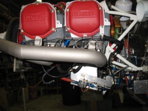
Here is the duct system in the final form.  Some paint and it will look great.

Oct 11 2010

Wiring has started

Today,  I found myself getting a bit excited working on the plane because all the MAJOR issues have been solved and all the pieces of the puzzle are fitting nicely together.  Basically there are 3 major areas to complete.   Induction, hoses, wiring.  I still have a few minor items to do, but those will be easy as I already have all the installation issues with them (ELT install, Fire suppression system install) worked out.

The old inlets were cut off, and a fuel servo and oil cooling ducts (started today) will be constructed.  It will take 3 days to complete only because I have to let the fiberglass cure between the various the layup steps. 

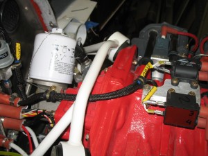
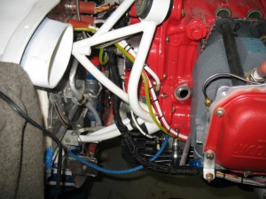
This will be the new home for the fuel servo inlet.  Some hose needed to be rearranged to accommodate the duct.

Woo Hoo, wiring in earnest has finally started. I want to get the engine monitoring system installed first as I am still waiting to get the instrument panel back from the printers before I can work on the front of the plane.

Oct 09 2010

A MONSTER engine

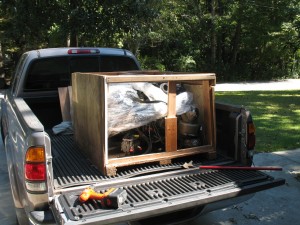
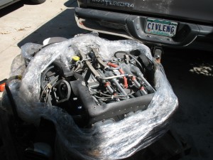
I finally received the MONSTER ENGINE  (ME), a six cylinder IO-540 engine for my ultimate plane from Oklahoma.  She is fuel injected with 270 hp of pure power and weighs in at a robust 400 lbs.  The ME came of an Aztec twin engine plane.  What a brut!   The shipping weight was 607 lb with the turbocharger (which I am not going to use).   I love the IO-540’s.  They just purr when running and are as smooth as silk.    Beside I want to go FAST!!!

The day was spent sealing all the opening cranking it with preserving oil in it.  Hopefully with the precautions I have taken to prevent rust, she will be in great shape when I finally start it up years from now.  Sometimes a good deal is hard to pass up!

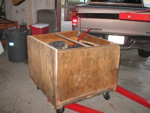
Moved to the my hangar.  The wheels are recycled from my oil cart I rebuilt.  
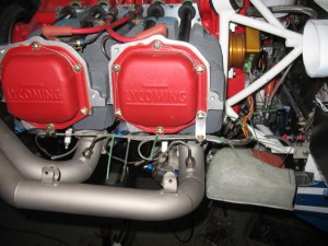
 

Sometimes I suspect I am a closet junk hoarder.  There is actually a TV show about people that hoard all kinds of stuff.  That’s me!  I HATE throwing away wire bits, scraps, little switches, motors, etc because RIGHT after I throw the junk away when working on a new project, I realize it could have been used.    I threw away the old engine baffles on the plane today.  Just more junk in the shop to deal with. 
Wouldn’t you know it this afternoon, I realized it had been a mistake because I needed the scrap aluminum.   Crap….. that will teach me.