Category: Electrical

Oct 28 2010

Wind Generator Dedication

Today was interesting.   At lunch I attended the official dedication of the soon to be built national wind generator gear testing facility which will be run by Clemson University.   Development of the facility is being funded through a $45 million grant from the U.S. Department of Energy and an additional $53 million in private donations. Within days of announcing plans for a testing facility last November, IMO Group, a German company that makes wind turbine parts, announced it was opening a plant in North Charleston that would create 190 jobs.

It is  predicted thousands more jobs may be just around the corner as the Institutes 100-plus acre campus on the site of the former Charleston Navy Base grows.  When completed the site will be able to test the largest of  gear trains for off shore wind generators to failure.    One speaker said this is one of the most important sites for wind energy research and development in the country.  Plenty of pomp and circumstance for the crowd, but where is the food???

We were addressed by our senators, congress men and the city mayor.     The speeches were short and to the point.  Just how I like them.   Hum… food? It is lunch time.

This picture turned out interesting.  The piles of orange dyed sand (Clemson colors) seemed to glow like pots of gold.  Since the building is already built, officials will dig into the sand piles with shovels for the smiling money shot….

A local high school or possibly elementary school (maybe kindergarten?) band provided the dedication music…. all I can say is they tried hard.    Where is the feaking food???  I’m hungry.

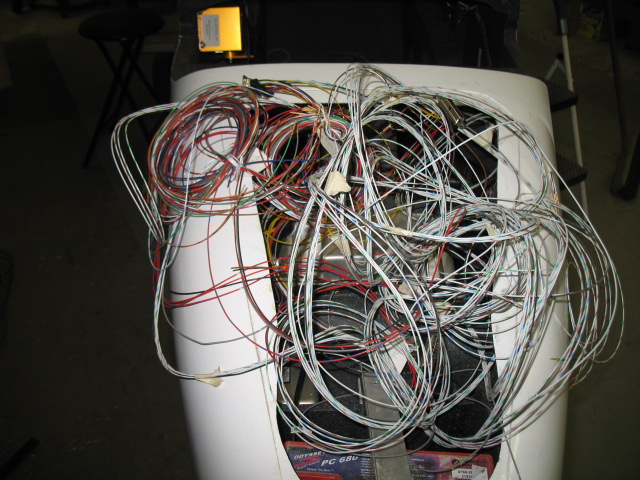
The headrest area is done.  I now have the EIS, aft battery, fuel level indicators, power distribution (aft), electronic ignition’s and starting system finished.   This is how it looks before the beauty panel.

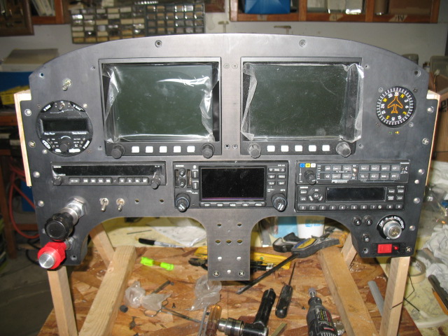
This is with the cover panel in place.  You  will never have to get to the electronics behind the panel unless a part fails.  I’ll letter the panel with the obligatory warnings, fuse sizes, etc to dress it up a bit.

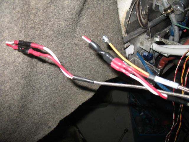
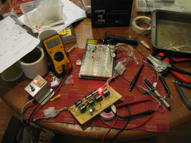
The coils for the Lightspeed ignition are done.

BTW:  There WAS NO FOOD at the$98 million dollar dedication.  Cheap bastards……

Guess I’ll have to buy my own lunch.

Oct 25 2010

EIS done

The engine information system is done!  Ya!  To go from such a mess of wires to this is great.   Now begins the fun of connecting the battery and fuse to the loads.

Black sleveing was put on the majority of the wires where possible.

Looking good now. 

Oct 18 2010

CHT wiring trick

There is not a lot to show you when wiring a plane.  Maybe a jumbo of wire, then everything neatly organized.    Here is a little trick I have been using for installation of CHT’s and EGT’s.

You have to connect the probes up to the readout equipment.  Normally, one uses ring connectors or 1/4″ push on connects as most do.  I think they are bulky and unnecessary. 


What I like to do is to do an inline splice with a sub-D barrow pins.  Just put pins on the wires, put heat shrink over them to hold them together and you are done.  After heat shrinking the junction, I always heat shrink the two wires together as a pair.  It make a great connection, there is very low voltage through the joint and since the sub-D pins are gold they will last the life of the plane. 

These joints makes the wiring  job not only look better, but are very compact.

The stbd side of the engine is done.

Oct 11 2010

Wiring has started

Today,  I found myself getting a bit excited working on the plane because all the MAJOR issues have been solved and all the pieces of the puzzle are fitting nicely together.  Basically there are 3 major areas to complete.   Induction, hoses, wiring.  I still have a few minor items to do, but those will be easy as I already have all the installation issues with them (ELT install, Fire suppression system install) worked out.

The old inlets were cut off, and a fuel servo and oil cooling ducts (started today) will be constructed.  It will take 3 days to complete only because I have to let the fiberglass cure between the various the layup steps. 

This will be the new home for the fuel servo inlet.  Some hose needed to be rearranged to accommodate the duct.

Woo Hoo, wiring in earnest has finally started. I want to get the engine monitoring system installed first as I am still waiting to get the instrument panel back from the printers before I can work on the front of the plane.

Sep 07 2010

Panel milling

Today was dedicated to getting the panel finished so I can send it out for lettering.  It has the longest lead time to get back to me.    The radio cans were positioned and the nuts were bonded to the side boxes to hold everything in alignment after disassemble.

Next was milling the backside of the .200″ thick carbon panel down to .125″ thick in for some of the switches.   Some areas were milled to .060″ for LED lights.

Two “Data Ports” were machined into the panel.  These ports will allow the pilot to upload flight plans, software, maps, etc to the Grand Rapids Flight system, as well as down load recorded flight data (air and engine) to be analyzed after landing.

The switch at the bottom of the panel is actual an air valve which will allow the pilot to have an “alternate static” port in case the fuselage port gets plugged.   I think I may look for some different knobs.  I don’t like the size of these all that much.  I think they are a somewhat big.

I started laying out the wiring for the GTR system.  All these wires are in addition to the ones in the back of the plane which are for the engine monitor.    This doesn’t come close to what needs to go into the plane.    When I was a kid I used to think it was fun to unravel a mess of tangled string.    This wiring rats nest makes me think of those days long ago…..

Sep 03 2010

The money shot…

Finished installing the cans for the radios today and wanted to see how the panel looked together (for the most part).  Found a minor lettering issue I’ll need to resolve before it is sent off.  This is certainly the most advanced LongEZ panel in the world.  I have never seen an EZ or Berkut with this much electronics.  It is going to be a blast to learn to fly this bird with all the computers on board….

Wow, I sure have a lot of conectors to hook up to wire the panel….. should be fun!

Sep 02 2010

The panel is back

I finished up the work on the WVO car controller.    I built a test stand to simulate all the connections and switches of the car and dang it, the thing worked as I originally designed it.  I dont know why I thought it was a bad design.  After a few hours work on the timer circuit it now works perfectly.  

Basically, in AUTO, the WVO system now waits for the coolant water to get up to 60C, turns on the oil supply valves, turns on an electric oil heater to keep the oil a minimum of 50C (it cycles as necessary). 

If the fuel in the supply tank gets to 1 gal, it shuts everything down. 

When the car is turned off in AUTO the system closes the oil valves and keeps the engine running for 30 sec to purge out the WVO before it turns the car off.   Very cool…  The next step is to install LED’s and the switch in the dash with some nice lettering to make it look good.  It is amazing to me that a commercial unit which does the same thing this does cost $350.  Mine cost about $25.

The engine is now on the plane.  It really looks good now with the newly painted engine mount and engine.

The is a close up of the firewall penetrations.  After all the wires are run, I will clamp the firestop tubing around the wires.

The insturment panel came back to me unletter but with some nice glass work done around the leg openings and radios.  I spent all day fitting the radios to the panel so they would have exactly 1/4″ exposure from the panel.

 Tommorow, I’ll finish screwing the radio boxes to the panel and some other detail work which needs to be done prior to sending it off to be lettered.

Aug 30 2010

Working on a sick friend

Yesterday, I stared making a new batch of fuel probes which have been selling surprising well.  Thats when I found Mr. Lathe was very sick…..  Yikes, he is one  of my best friends in the shop!  

Stop the presses, this is an emergency!!   

After downloading the wiring diagrams from the web, I spent hours trying to figure out how those dam low paid chinese gals wired him up.  At least the numbers were in english.  Imagine, hand drawings of the wiring!    Chicago Tools (Harbor Freight stuff)=Made in China junk (but the price is soooooo cheap).

After a few hours trouble shooting, I found a contractor had gone bad which has been ordered 2 day express from Calif.   I should be back up and going on Friday!  Woohoo!  

Replacing the contractor out (upper right box) from this wiring mess is going to be a challenge.  I think I would rather take part the dash of the car again.

After the trouble shoot bout with Mr. Lathe, I started back reassembling the engine.  It looks really good now.

Before I remount it on the engine, there was some firewall work to be done such as pulling wires through my bulkhead fittings.  What a mess!  At the top is a 95 db backup beeper.  It is great for scaring birds on landing and warning people at airshows to keep out of my freaking way!

This is a piece of 1/8″ copper tubing which will be for the manifold pressures sensor.  I prefer putting a copper tube though the bulkhead instead of just running a piece of rubber tubing.  I think it is safer and is less trouble some when removing the engine. 

I also stared working on the wiring of the engine information system area.  It is starting  to get fun now.    I love wiring!

Aug 20 2010

Oil Pan is back

The oil pan is back from the machine shop.  They only charged $80 for machining the flange flat.  I hate oil leaks and I am sure it was worth the effort and money.

I have a long list of things to do from painting the engine accessory case to mounting ground blocks before I can put the engine back on the firewall.  It was really to my advantage to take the engine off the plane (took less than 1 hr) to gain access to the firewall and the front of the engine. 

This shows the firewall through bushings I made and installed.  Since they are high temp fiberglass products, they are floxed into the firewall.  They are nicely rounded on each end to prevent chafing of the wires and possible contact with the grounded firewall.    The starter cable has over 600 amps flowing through it and I want to make sure there is no possible way to contact the firewall, ground out, and start a fire. 

The bushings are 1″ long with a 1/2″ flange exposure into the engine compartment so I can put firestop on the end. In the unlikely event of an engine fire, the firestop will prevent fire/smoke from entering the cabin from the wire openings.

Aug 18 2010

Firewall Repairs

Today I put in some long hours and got a lot of things done. 

While sanding the engine mount to prep it for painting, I found an vent hole which had never been closed off because a support rod was in the way.  I just drilled a second hole, welded it closed, filled the tube full of linseed oil and closed it off.

Since I had the engine mount off, I took the opportunity to close off any unnecessary hole in the fire wall.  This was a big one the original owner had cut to allow for a DB-25 plug for the ignition system. 

I tired welding, but the metal is so thin I just couldnt get a stable arc, the fiberfax just vaporizes and blows holes in the weld.  Hum…what to do??

I decided to install cover plates over the holes with SS rivets.  It worked out much better. 

this plate closes off some holes used for the ignition system high tension leads.

There was a couple of big ones just below the cable pulley.   Closed off too.

I finished painting the engine mount.  Hopefully I’ll install it tomorrow if the paint is hard enough.

This is a one of four firewall bushing I machined out of a high temp fiberglass rod.  I am using these bushing to for all wires going through the firewall to prevent any contact (shorting) of the wires.  They are made long on the engine side so I can put a firestop sleeve over the exposed bushing and clamp it to the wires.