Nov
08
2010
I decided to take a few pictures of the current work as I am going to take a couple of days away from the work to get a some chores done. Sort of a working vacation.
Here is the shape of the outlet duct I came up with. It is a much smaller outlet than original and compresses the air prior to injection in the airstream. I wanted a slight kick out to create a low pressure area just in front of the outlet (somewhat like my plane which I know works well. When I start flying the bird, I’ll record some data reading to see just how well it compares to my plane.

the oil cooler was tilted 25 deg from orginal. Te final effort is creating the inlet duct. Some sanding and it is ready for paint!

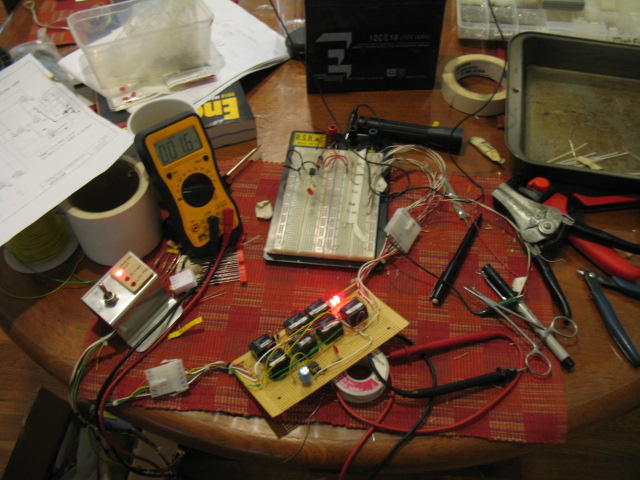
I made the decision to organized all my electrical stuff. It is much more efficient to have everything inventoried, organized and easily assessible to speed up electrical work. I was getting frustrated looking for stuff asit was slowing my progress down.

A table full of … stuff…. Now I have to sort through all this stuff and get it organized. This will take HOURS (but time well spent ).

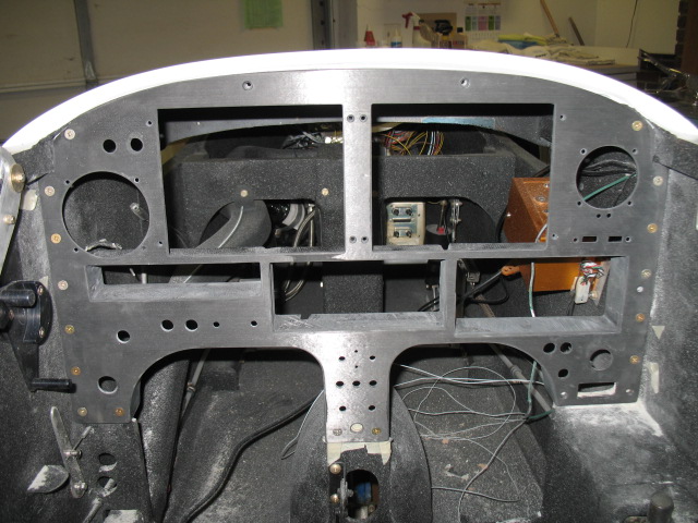
I also wanted to populate the instrument panel to see how it would look and it is freaking beautiful. This picture doesn’t even begin to do it justice. It it going to look fabulous when installed in the plane!

I am extremely pleased with the result.
Nov
01
2010
I have to take a necessary break from the wiring to wrap up a few last items. The oil cooling, the 406 ELT and final installation of the fire suppression system.
I didnt really like the straight down (original plans) type oil cooler installation. There is no expansion of the inlet air (increases pressure) or contraction of the air (pressure recovery) so I decided to tilt the oil cooler 25 deg to allow a smoother flow of air into and out of the cooler. I also replace the cooler with a more efficient Stewart Warner.
First step is establishing a base plate and shape of the outlet duct.

Next is to glass it.

I now have to build flanges on the duct to bolt the oil cooler on.

The flanges have been glassed. Tomorrow, the cowl will be glassed for the outlet air flow after which the inlet duct will be fabricated.

In between all this, I installed the back seat electric panels. The came out exactly as planned. Very cool looking!

Both panels have a 12 vdc constant on plugs (so you can charge your phone at an airshow).

Boo..
Oct
16
2010
The last few days were spent working on the fuel servo inlet duct. I wanted to use the armpit scoop on the right side of the cowl instead of cutting through the firewall into the hell hole.
After visualizing what was needed the part had to be carved out of foam. First I had to carve the part out of foam and glassed.

After a few hour under a vacuum, the part was read to be revealed.


Here it is with the foam still on the inside.

Tony stopped by again to check out the work. He thought it all looked “smashing” and “very clean”.

Here is the duct system in the final form. Some paint and it will look great.

Oct
11
2010
Today, I found myself getting a bit excited working on the plane because all the MAJOR issues have been solved and all the pieces of the puzzle are fitting nicely together. Basically there are 3 major areas to complete. Induction, hoses, wiring. I still have a few minor items to do, but those will be easy as I already have all the installation issues with them (ELT install, Fire suppression system install) worked out.
The old inlets were cut off, and a fuel servo and oil cooling ducts (started today) will be constructed. It will take 3 days to complete only because I have to let the fiberglass cure between the various the layup steps.

This will be the new home for the fuel servo inlet. Some hose needed to be rearranged to accommodate the duct.

Woo Hoo, wiring in earnest has finally started. I want to get the engine monitoring system installed first as I am still waiting to get the instrument panel back from the printers before I can work on the front of the plane.

Oct
09
2010
I finally received the MONSTER ENGINE (ME), a six cylinder IO-540 engine for my ultimate plane from Oklahoma. She is fuel injected with 270 hp of pure power and weighs in at a robust 400 lbs. The ME came of an Aztec twin engine plane. What a brut! The shipping weight was 607 lb with the turbocharger (which I am not going to use). I love the IO-540’s. They just purr when running and are as smooth as silk. Beside I want to go FAST!!!

The day was spent sealing all the opening cranking it with preserving oil in it. Hopefully with the precautions I have taken to prevent rust, she will be in great shape when I finally start it up years from now. Sometimes a good deal is hard to pass up!

Moved to the my hangar. The wheels are recycled from my oil cart I rebuilt.

Sometimes I suspect I am a closet junk hoarder. There is actually a TV show about people that hoard all kinds of stuff. That’s me! I HATE throwing away wire bits, scraps, little switches, motors, etc because RIGHT after I throw the junk away when working on a new project, I realize it could have been used. I threw away the old engine baffles on the plane today. Just more junk in the shop to deal with.
Wouldn’t you know it this afternoon, I realized it had been a mistake because I needed the scrap aluminum. Crap….. that will teach me.
Oct
07
2010
Here is a quick update
The panel is now in Montana being lettered. The initial pictures sent me by Aerotronics showed the lettering was not put on straight. It was a bit skewed. A quick call to the company and they are redoing it again. This is certainly the panel from HELL!! It is cursed! I’ll be afraid to to touch it when I finally get it back as some of the luck of the ??? might rub off.

The engine is mostly put together. Intake, exhaust, alternator, fuel injeciton are all done. The downdraft cooling system has not been competely installed as I need to put some fuel in the plane and purge the lines prior to buttoning it up.

I have run the power lines to the alternator and starter. All the rest of the wires are temporarily mounted to test wire runs.


The final step on the engine to find a home for the oil cooler and fuel injection air intakes . I have found a good spot to build inlet plenums and should only take a few days to complete. The bad news is I have to use some SCAT tubing (yuck) on one air intake the good news is when done I can finally get to the wiring! Cant wait.
Sep
20
2010
The panel had the last fitting today. Found some issues I still needed to correct but I think it is just about done! Yeah! Although the panel easily is removed from the plane with the radio cans in place with no wires, I’ll need to write a procedure up on exactly how to remove all the interferences prior to actually taking it out. There sure would be a number of steps….

It is quite impressive with everything in place. The Trio Autopilot head was sent back to Trio because the display was not working. I also wanted to get it upgraded to the latest firmware (which includes support for Grand Rapids GPSS and GPSV.

Also completed to day was the baffling mods for the engine. As soon as the instument panel is set off for lettering, I’ll be able to complete the engine work.
Sep
10
2010
The last few days have been total devoted to getting the panel ready for lettering as I thought the effort would be short and easy. While looking at the panel I decided I didn’t like the big chrome bezels of the LED lights. I floxed the holes shut and redrilled them to accommodate simple LED holders. I dont like the knobs either, so I am going to machine some that I like. It is easy to do on a lathe. I also cut the shaft of the potentiometer control shaft off so I can reduce the exposure of the knobs.
The before look

The after look.

I decided it was best to fully assemble everything to make sure there were no surprises. The nutplates for the panel were floxed in and I like the stiffness of the panel when placed in it’s frame and secured.

Note the gold box in the above picture (the autopilot elevator servo.
When looking from the other side I noticed it was going to hit the com panel and transponder radio cans. FU****K!! The servo has to go.

You can see the carbon box just forward of the servo into which the radio can is secured. Bye bye, servo….
Not only did the servo hit but when I changed out from a Garmin 327 to a Garmin 330 transponder, I found the transponder’s can was 2.5″ longer than what I had planed for which made the can hit the elevator control rod. SH*T!

Major redesign time! Hum, IF I switch the places of the com and transponder then the com panel (with the shorter can) will allow me to gain the clearance I need for the control stick. After a few hours work…done. Clearance is good now.
Since the panel is taking longer than I anticipated to finish off, I took a few hours to to get some critical measurement from the engine I needed to send to Airflow Performance so I could get the fuel lines made. AFP currently has the fuel servo for a minor change, and they were waiting for me to call them with the injector line lengths so they could build them and ship all the stuff back to me. I finished making the cylinder cooling plates (an improved design to the down draft system) and took some heavy wire to simulate the fuel lines and route everything to make template lines.

After a while of bending, cutting, rebending, etc I was satisfied with the routing and placed my order for the lines. They should be here by next Wed. I’ll then be able to fully assemble the engine!
I found a new home to re-install the autopilot servo. Here, I am using the fiberglass spring template to make a new control arm for the elevator torque tube. I’ll attach the servo to this tab. It will act as a carbon control arm for the servo.

Sep
02
2010
I finished up the work on the WVO car controller. I built a test stand to simulate all the connections and switches of the car and dang it, the thing worked as I originally designed it. I dont know why I thought it was a bad design. After a few hours work on the timer circuit it now works perfectly.
Basically, in AUTO, the WVO system now waits for the coolant water to get up to 60C, turns on the oil supply valves, turns on an electric oil heater to keep the oil a minimum of 50C (it cycles as necessary).
If the fuel in the supply tank gets to 1 gal, it shuts everything down.
When the car is turned off in AUTO the system closes the oil valves and keeps the engine running for 30 sec to purge out the WVO before it turns the car off. Very cool… The next step is to install LED’s and the switch in the dash with some nice lettering to make it look good. It is amazing to me that a commercial unit which does the same thing this does cost $350. Mine cost about $25.

The engine is now on the plane. It really looks good now with the newly painted engine mount and engine.

The is a close up of the firewall penetrations. After all the wires are run, I will clamp the firestop tubing around the wires.

The insturment panel came back to me unletter but with some nice glass work done around the leg openings and radios. I spent all day fitting the radios to the panel so they would have exactly 1/4″ exposure from the panel.

Tommorow, I’ll finish screwing the radio boxes to the panel and some other detail work which needs to be done prior to sending it off to be lettered.
Aug
23
2010
Yesterday started off with a quick 10 minute trip to a “Flyin Breakfast” at Monks Corner. I helped a little with the food and setup, but mainly I just enjoyed a great early morning flight which was very nice.
I wanted to show you the progress on the the construction of Boeing 787 Dreamliner plant. They are still adding to it. The size is just immense! I have to pass it to go to my hanger, so I see the progress on a regular basis.

Only about 40 people showed up at the breakfast. Not many planes either as I think the weather (low clouds) may have put some attendees off.

I took the opportunity yesterday to finish off the oil tank part for my grease car. I spent hours welding aluminum and finally thing I am starting to “get it” on welding this metal. It certainly takes a lot of practice. At least the welds are not coming like big blobs or melting through. It takes a huge amount of current (175 A) and the TIG handle would get so hot I would have to let everything cool down ever 15 minutes. The inside of the tank is built with a baffle and a coil of 5/8″ Al tubing which I can circulate hot water through for additional heating of the cooking oil if I ever decide to use it (cold weather ops). I always like to plan ahead.

I have been using a 5 gal gas can for the last few months which conveniently fit into a well on the car for the cooking oil. It held 5 gal of oil and gave me a range of about 110 miles.

The new tank holds 8 gals of oil and it also has a low level alarm which activates at 1 gal. It looks a lot better than my red tank.

Speaking of red…. I wanted to paint the engine one color since the case was red and the accessory case was gray. It took a lot of time to paint but the engine is again one color. Tomorrow I’ll replace all the bolts with new ones .

The new look. Kind of like it..


