Category: Engine

Aug 20 2010

Oil Pan is back

The oil pan is back from the machine shop.  They only charged $80 for machining the flange flat.  I hate oil leaks and I am sure it was worth the effort and money.

I have a long list of things to do from painting the engine accessory case to mounting ground blocks before I can put the engine back on the firewall.  It was really to my advantage to take the engine off the plane (took less than 1 hr) to gain access to the firewall and the front of the engine. 

This shows the firewall through bushings I made and installed.  Since they are high temp fiberglass products, they are floxed into the firewall.  They are nicely rounded on each end to prevent chafing of the wires and possible contact with the grounded firewall.    The starter cable has over 600 amps flowing through it and I want to make sure there is no possible way to contact the firewall, ground out, and start a fire. 

The bushings are 1″ long with a 1/2″ flange exposure into the engine compartment so I can put firestop on the end. In the unlikely event of an engine fire, the firestop will prevent fire/smoke from entering the cabin from the wire openings.

Aug 18 2010

Firewall Repairs

Today I put in some long hours and got a lot of things done. 

While sanding the engine mount to prep it for painting, I found an vent hole which had never been closed off because a support rod was in the way.  I just drilled a second hole, welded it closed, filled the tube full of linseed oil and closed it off.

Since I had the engine mount off, I took the opportunity to close off any unnecessary hole in the fire wall.  This was a big one the original owner had cut to allow for a DB-25 plug for the ignition system. 

I tired welding, but the metal is so thin I just couldnt get a stable arc, the fiberfax just vaporizes and blows holes in the weld.  Hum…what to do??

I decided to install cover plates over the holes with SS rivets.  It worked out much better. 

this plate closes off some holes used for the ignition system high tension leads.

There was a couple of big ones just below the cable pulley.   Closed off too.

I finished painting the engine mount.  Hopefully I’ll install it tomorrow if the paint is hard enough.

This is a one of four firewall bushing I machined out of a high temp fiberglass rod.  I am using these bushing to for all wires going through the firewall to prevent any contact (shorting) of the wires.  They are made long on the engine side so I can put a firestop sleeve over the exposed bushing and clamp it to the wires.

Aug 16 2010

Engine Mount Mod

I finally received the beautiful oil pan from Calif I designed.  When I started to bolt it up to the oil pan I found out the fuel servo was hitting the engine mount???  WTF????  After I checking it out I found out the fabrication company had welded on the mounting flange at 5 deg not 10 deg as I specifically directed in the manufacturing drawing I sent.  What to do.  I thought about machining the flange to 10 deg, but decided against that coarse of action as it caused other mounting problems with the servo and finally chose to modify the engine mount instead.

Here you see the fuel servo hitting the mount.  It still needs to move upward another 1/4″ to bolt on the oil pan…

The engine being removed from the mounts.

I chose to grind out part of the tube.  The 4130 tube is .050″ thick and I was surprised to see LOTS of linseed oil in it as is required to prevent internal rust.

I welded on a plate of 4130 steel .063″ to the mount after grinding away the cross tube.  It looks like it is ground at an angle but that is becuase the tube is tilted  when mounted.

The finished clearance.  I LOVE welding 4130 steel.  If you want to get good at welding, just weld Aluminum for a while.  It makes welding steel or stainless steel seem so easy a cave man can do it.   I now have 3/8″ clearence all the way around the fuel servo.  More than enough mount clearance.

Re-injecting about 1/4 cut of linseed oil back into the tube prior to sealing.  Tomorrow I’ll take the oil pan to the machine shop to have the mounting flange machined flat (should have been done in CA) as it warped during the welding process and repaint the engine mount. 

Total mod time 4 hrs.

Aug 15 2010

Fuel Probes Fiasco

I have been getting more orders for fuel probes almost exclusively through word of mouth.  Today I decided to mass produce a bunch of them to have an inventory of parts.  I have changed my original design somewhat to account for the spacers I am now getting from Princeton Probes.  It is supposed to save me building time.   What a fiasco!

I made about 75 bases which took about 3 hrs.  They looked great but unfortunately the holes ended up being too big even though I had drilled them severely undersized.  Shit….

They are now trash.   I even tried welding the tubes into the bases, but was not happy with the results.  Welding the tubes to the bases is still a possibility, but I can not use the ones I made.

I did end up making about 14 probe bases (4 of which are sold).

Sum total of 8 hrs of work…. two probes completed. 

My next step is to get some very small reamers and try liquid nitrogen to chill the tubes prior to insertion into the hot bases (creates a very tight bond of the two parts).   Might also try threading the tubes.   I hope that I can eventually come up with a better production methodology or I wont be able to make them at an affordable price.  It wont be worth my time….

Apr 20 2010

California Bound

Today is the last day of work before a business trip to Los Angles tomorrow.  It is a fairly short one and I’ll be returning Friday night….

It was a very busy day today.    First task of the day was shortening the oil dip stick tube.  After cutting the tube to the correct length (and a little reduction of the diameter on the lathe, a PVC connector was used to glue the pieces together.   A little black paint and it looks good and worked out very well.   I made a test sample (using the old tube) and could not get it to fail.   

Glued and painted.

 I have had to stop work on the engine compartment since I do not have a starter, alternator, oil pan, fuel servo or exhaust systems.    All these are in CA being fine tuned and modified.    That’s ok as it gives me time to focus in on other areas of the plane which needs attention.

I found the oil door to be hitting the inlet duct due to the off set hinge the orginal builder used.  After a bit of frustration trying to make it work, I decided to just remove it and go back to a standard hinge style.

It was quick to do and worked out great since the leading edge of the door was somewhat flat which allowed for a longer hinge. 

I also installed the bracket for the AHRS (electrionic gyro for the EFIS) and the Trio Autopilot pitch servo.   I had to install the canard to take measurements and really liked the look of it on the plane.  Installing the servo was interesting because I used my own instruction written years ago when I was a beta tester for Trio.  I tried a couple of different configurations to get the servo installed and when finally successful, I wrote up the methodology for other builders.  Naturally, I was a bit surprised at how well it worked and the clarity of the instruction.    Sometime I surprise myself.  

   When I get back I am going to finish off the canard and get it into primer.  I have completed almost all the glass work and installation of hardware so I am getting close to the painting stage.

***

Apr 19 2010

Cylinders 2 and 4 installed

Today was a long day of work on the plane.   It is hard to believe I have been working on the plane for a year and have put in 940 hrs on the project.    The number of hours is not surprising given the plane was completely stripped of everything except the basic structure and an extreme amount of customization and design work done.   I am determined to put out maximum effort for the next few months to get the project completed.  Besides, I really want to fly the bird!

Tony stopped by to learn the finer details of installing engine cylinders. 

Job well done!  Doesnt he look happy.

Cylinders 2/4 are installed.  I really like how the red crackle powder coating came out on the valve covers.

I needed to make a new bracket and bushings for the electronic ignition coils.

Simulated fuel injection lines were routed to determine the exact length needed.  They will manufactured by Airflow Performance after I get the fuel servo back from Calif to check on the fuel outlet position before I commit to the finial lengths.  I don’t want to be surprised when I put on the sump. 

This is the stbd side

The port side. 

Apr 07 2010

Cylinders Work

Cylinders #1 and #3 were installed today.  Had a bit of trouble with the push rods (there is a specific procedure to measuring and testing them)but in the end everything went together fine and all measurements are within specification.

Pat had the high compression pistons coated with a solid lubricant (they look black)  and the crown of the pistion ceramic coated.  It will give the engine a little more power.  He also had the new cylinder flow ported.  I checked them out and it looks nicely done.

The push rods were painted crackle black which makes them stand out a bit.  Once the baffles are installed, most of the push rod tubes will not be visible.

The inlet ducts were also painted crackle black.  I wanted them to stand out and not look like regular glass.  Yesterday, when I microed fuel probe area, I also filled the inlet ducts to smooth them out a little prior to painting.

The Stbd duct.  I like how the gold rivets stand out on the black… 

I am not going to install #2 and #4 cylinders until next Monday.  My buddy Tony wants to learn how to replace a cylinder, so we will do it together in a week or so.    It will cost him lunch at Aunt Bee’s.

The fuel probe installation has been microed and sanded.  A little paint and you’ll never know they are there.

Mar 18 2010

In the shop again

After the trip to CA, I was really messed up for a last few days.  I was extremely tired (time zone/daylight saving changes) when I got back,  the back was bothering  and the after affects of the dental work all hit me at the same time.  Ouch!   The trip to LA was just exhausting in many ways and I was sure glad to be sleeping in my own bed again.   I guess a bunch of factors all hitting at the same time just caused me want to relax since my head just wasn’t into the game.   I needed to do a lot of thinking and reflecting.     Thank goodness for good friends to bounce ideas off of.  Felt like doing absolutely nothing on the plane….

Today, I finally started feeling perky again, physically and mentally and decided to get back to work.  I want to get this bird out of the shop, so Pat can enjoy it.   He will really love the great flying characterists of canards.  What a great community too.

Before the CA trip the inlet ducts were glassed.  You can see the AL ring installed in the duct work of the STBD side to clamp the flex hose on after assembly.

The port side after glassing.  There is much more room to work with on the port side than the stbd side.   It is made a bit more bulky to allow the oil dip stick will penetrate this inlet duct.

After removing all the foam and glass and cutting them free I found I could get them on/off the engine with forward baffles installed!  Great now I can rivet the inlets to the Al air boxes instead of screwing them on as originally planned (it will look and perform much better).    Some more glass work is necessary for fine tuning and I’ll be done with them.

Mar 01 2010

Cooling Intets

On Sunday, I had a great day after church cutting up a downed tree and hand splitting the wood.  Actually it was a lot of fun using an ax instead of a log splitter.   A bit of work but great exercise. 


  I have shifted directions on the down draft cooling system.  After carefully looking at the cowl, Pat and I decided that the reduction of the height above the cylinder (due to the DD cooling plenums) did not warrant chopping up a beautiful cowl.  If I had not cowl it would be a different story.    Overall, I would save a considerable amount of time by keep the cowls a close to original as possible.  The first step is to reattach part of the original fairing. 


Foam was bonded to the inlets, shaped for glassing. 


There is an Alum ring (which you will see later which will be used as a support for a silicon vibration isolation tube.   The inlets both have about 12 sq in per side.   It should be plenty for cooling as it is about the same as my plane and my cooling works exceedingly well. 


Tomorrow, I will reshape this area, and start working on the inlet tube to the engine.   I feel shaping of the inlets is the hardest part of the down draft cooling.  The rest of the work is very simple.

Feb 01 2010

Still Baffled

Want to know how to change a nice new 2 ft x4 ft sheet of Aluminum

To a pile of beautifully cut and formed scrap pieces? 

All you have to do is to cut a pile of scrap pieces of paper and spend a LOTS of of time prototyping an entirely new down draft cooling design…..


I have spend the last few weeks trying to develop a down draft cooling system totally out of aluminum….  Why you ask.  Well if you think of production costs, it is much cheaper to make stuff out of aluminum then fiberglass.  Just look at the cost of RV parts.  They are really inexpensive when compared to fiberglass, hand molded parts.  Machines automate the manufacturing process. 

When I started assembling a DD system (change from updraft cooling), I felt the project needed to be modeling in Acad.   Faster than manually drawing lines on paper.  

Then I got a bug up my b*** and it became a real challenge after I hit on a really simple way to seal the engine.  Using seals around the push rod tube.   They were very difficult to get right but they work!  The tube baffle has grommets for the spark plug wires and fuel injection tube.  These seals proved to be the key for the box design.  Normally, the only hard part of sealing the engine for DD cooling is the case.  As far as the cylinders, they are all the same and there are no variations.   So why not just seal what you really need to seal.  

Overall, the purpose of this exercise is to to eventually design a kit of precut/bent parts which could be waterjet cut in mass, sold cheap, which allows a builder to assemble a VERY TIGHT down draft box and reduce plane cowl height.  Never been done for a canard aircraft.    What, we could actually have a something manufactured for our EZ’s which is cheap?  Who would have thought….    The kit is applicable to a 320 or a 360, pusher/tracker setup (I think it would be great for an RV).    RV’s could get rid of that red silicon seal material. 

What I like most is when the builder is trying to balance the cooling on the engine, you only have two cylinders to work (the box only covers two cylinders on each side) with and since the cylinders furthest from the inlet are the coldest, it is very easy to block the box at the half way point to raise the temperatures of the remaining cylinder.

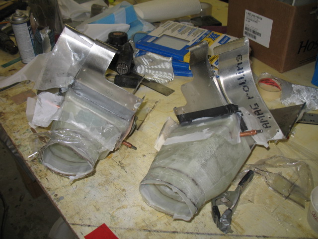
I went though a number of different designs…..

Design #1


Design #2

Design #3

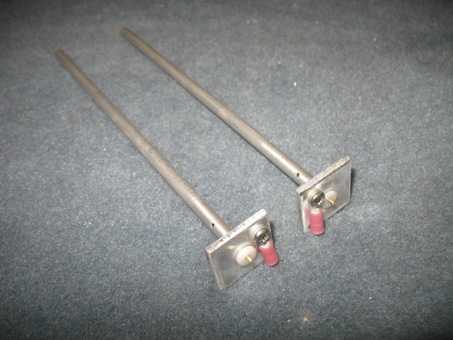
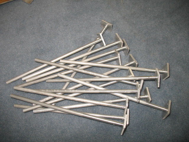
Many different tube seal designs, lots of paper prototype parts

Design #4

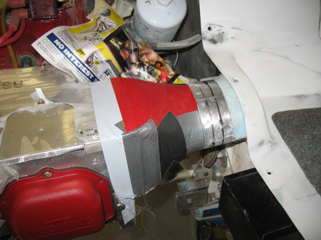
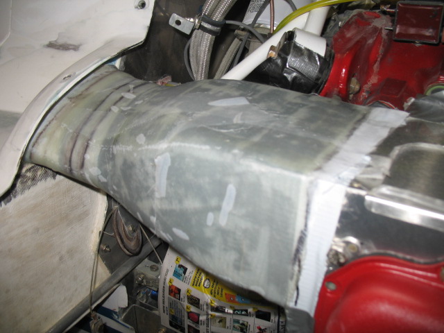
Finally, got it!  Here is the final design (the Al still it has the protective plastic on the metal).  Late after the cowl is finished, the plastic will be removed.

There is a sliding hatch held on with one screw which allows easy access to the spark plugs. 

All the parts just seem to majicly lock together almost like a chinese puzzle with a minimum part count.  Sometimes I even amaze myself!    Now the parts can be mass cut with a waterjet machine which means the kits will be very cheap and easy to reproduce. 

If nothing else and they are never manufactured, when I get around to modifying my other planes for DD cooling I’ll be able to make the DD cooling box in a day.    I’ll finish assembly of the box tomorrow.