Category: LongEZ Upgrade

Apr 07 2010

Cylinders Work

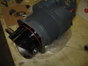
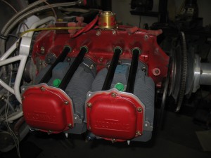
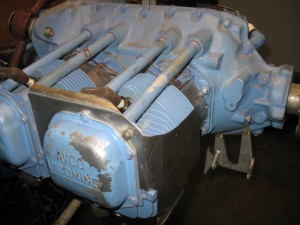
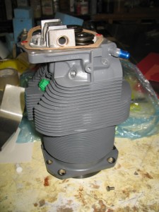
Cylinders #1 and #3 were installed today.  Had a bit of trouble with the push rods (there is a specific procedure to measuring and testing them)but in the end everything went together fine and all measurements are within specification.

Pat had the high compression pistons coated with a solid lubricant (they look black)  and the crown of the pistion ceramic coated.  It will give the engine a little more power.  He also had the new cylinder flow ported.  I checked them out and it looks nicely done.

The push rods were painted crackle black which makes them stand out a bit.  Once the baffles are installed, most of the push rod tubes will not be visible.

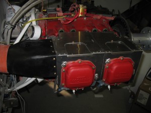
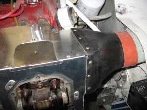
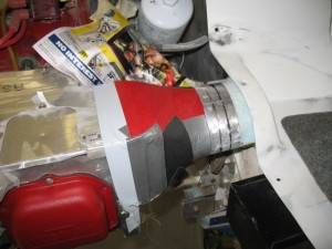
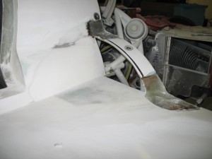
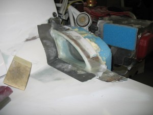
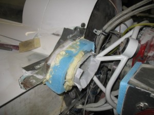
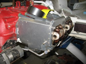
The inlet ducts were also painted crackle black.  I wanted them to stand out and not look like regular glass.  Yesterday, when I microed fuel probe area, I also filled the inlet ducts to smooth them out a little prior to painting.

The Stbd duct.  I like how the gold rivets stand out on the black… 

I am not going to install #2 and #4 cylinders until next Monday.  My buddy Tony wants to learn how to replace a cylinder, so we will do it together in a week or so.    It will cost him lunch at Aunt Bee’s.

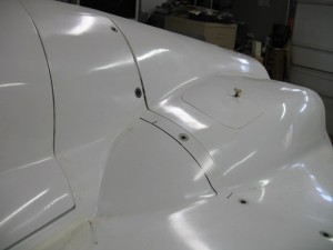
The fuel probe installation has been microed and sanded.  A little paint and you’ll never know they are there.

Apr 06 2010

Fuel probes are installed!

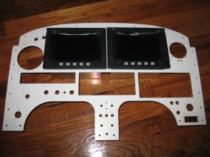
Today,  I reached a few personal milestones by shipping off the instrument panel and installing two capacitance fuel probes of my design.      There is a a bit more to this story so get ready for a long read. 

First
I completed everything left to do on the instrument panel, wrote the testing and modification procedure for Pat, then shipped it to LA by FedEx 3 day.  P1 Prototypes (Pats composite fabrication company) has some shop time available (by his top technician) and he will personally build and attach radio brackets, leg opening flanges and clear coat the panel to my specifications.   It will come back ready to install.  How cool is that?

Second,
For years, while visiting airshows, I always checked out vendors looking and comparing various remote capacitance fuel probes (because I wanted some in my bird).   They were all very simple, small and reliable, and VERY EXPENSIVE ($150- 175 each) and I am too dam cheap to spend mucho dinero for a simple product which doesnt even include the electronics.   Ouch!   A few months ago I had an idea to make a probe setup specifically designed for a canard installation.   Finally, a fuel probe which would work in a non-Cozy canard.

Non-Cozy canards are built in way which does not lend itself to the installation of capacitance fuel probes (CFP) .    Cozy’s have a nice fairing forward of firewall which can be used to cover and hide the probe installation.   I have seen a few attempts to install probes in LongEZ’s, but have never liked the final look of the avaliable products.   Either they are puck type which is harder to seal, or they are WAY too tall to hide.    The only advantage to these systems is that they are removable after installation.    Mine are not, but what can go wrong with a tube and with a wire in it?

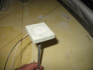
Initially the design started with a probe.   A proper installation requires a very short probe less than 3/8″ tall.   The shortest probe I have seen was at least 1.5″ tall (or a puck at 1″ tall).  This probe’s height is sized to fit into the space of the 10mm foam core of the strake.   After many designs a working prototype was finished.

Less than 3/8″ tall it can be easily and quickly installed.  Is is completely invisible after installation and fits nicely in the foam core space.

A test cell was built to check the height dimension,  the dielectric constant of  two epoxies and the accuracy of the voltage output for two common fuels I use,  MOGAS and AVGAS.
Next, some electronics are needed to make these probes work.

I knew Princeton Technology built capacitance electronic fuel probe modules.   They build puck styles and other various remote probe styles and has a great reputation.   At the SNF airshow last year,  I talked to  Todd Stehouwer (the owner of Princeton) and finally convinced him to let me help him.   I could easily see a wide open market for an EZ probe system.    As many canards owners rewire their canards to install improved electronic systems such as Grand Rapid, Dyson, ECI, the market was wide open for a new product line.   All that was needed is Todd’s help to develop an EZ specific electronics product so he could sell product to make mucho dinero   Why did I do this?   Because I freaken needed some for myself  and someday I might need his help.  “Pay it forward”!

After many months of emails, calls, a few miss steps, Todd finally completed the engineering for the module needed allow this probe to function.    He used the test cell I sent him (MGS with AVGAS) for setup, calibration and testing.    The nice thing about his electronics module is that it has FIVE calibrations point to fine tune the electronics to your fuel tank profile and can be used with either AVGAS or MOGAS (you have to recalibrate it for the dielectric of the fuel).   

Well, call me an over cautious engineer, but I always have to check everything out before I put my cra*k, oops, foot out there to get stepped on.    I want to be sure I would be as happy with this design as if someone else presented me with a similar design for evaluation.

Here is a couple of issues of concern to me.

1.  Will fuel resistance of either WEST or MGS  (two common epoxies) work for this application?  I know MGS is multi-fuel safe.  A quick call to WEST Tech Support confirmed  WEST resin is fuel safe for AVGAS or MOGAS (NO Ethanol) fuels.   My main concern was the possiblity builders might no have MGS available, but most of us have WEST handy (or can easily go to a local boating store to buy a pint).  Epoxy/fuel check …good.

2.  Next does the epoxy affect the overall capacitance of the system?   Epoxy is a dielectric.  Is the dielectric (hence functionality) a factor and/or epoxy dependent?  I built two test cell to evaluate.  One using WEST and one using MGS epoxy. 
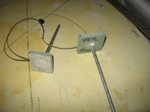
After testing by Jack Wilhelmson and myself,  we found the epoxy made no difference to a calibrated probe in AVGAS or MOGAS.  Epoxy/Capacitance  check …good.

3.  Does the OVERALL system work reliably?  A test rig was set up and after gathering about 40 data points, I found overall the system works very well.  Voltage output for different heights were exactly repeatable about 85% of the time.  Sometime, it would just be off just a small amount 0.1-0.2 V or so, but no surprises.  I dont even know if that small a voltage would make a difference on a display.   This could be partly due to the difficulty of measuring the capacitance on a 7.75″ probe (the height of the strake) or the accuracy of the VOM.    Todd and Jack also tested the electronics.    Accuracy check.  …good.

Here you see the probe sitting in MOGAS at “FULL”  tank  level in my home test rig.  The voltage shows is 4.96v.  
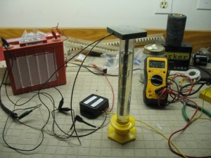
To calibrate the system, just fill your tank to your personal “empty” level …press “SET” to lock in “Empty” point.  Fill the tank to the 1/4 level (or fuel gals)… press “SET”.  Repeat for 1/2, 3/4 and FULL.    Took just a few moments. 

Before you read further be warned, in my opinion everything in life has Ying, Yang….. the Black and White,  Good and Bad sides.  Here is this probe’s good/bad side.

The BAD:
1.  This is a PERMANENT install.  Everything is glassed into place.  You’ll never get it out.  Be smart and careful with the installation.
2.  If it stops working, you’ll have to abandon the exiting probe and install one in a new location.  

The GOOD:
1.  It is the only probe/electronic system specifically designed and built for a canard aircraft (Varieze’s to Cozy 4)
2.  The electronics are easily removable/serviceable (there is a quick disconnect on the fuel probe wire).
3.  It is VERY easy to install in a few hours.  Installing two probes took me around 2 hrs and I didnt know what the heck I was doing!

The UNKNOWN:
I have done my best to ensure this solution will work.    I wanted to test everything and be as absolutely confident as possible before I spent the time installing it.   Before I recommend it with complete confidence,  I  still need to complete the wiring of the plane, calibrate the system with 100LL and gather many data points comparing the sight glasses and electronic output over an extended period of time .  

If you are a experimenter like me who likes to try new things (testing indicates this system will work) then go for your own installation.  If you are a timid soul, then I would recommend waiting until I start flying this bird and get some real life data before thinking of installing it.

The Installation:
Now the fun part.  The entire process took about 2 hrs start to finish.  

Measure and cut a hole in the outer skin of the plane.
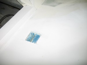
Remove the foam to the inner skin.  Sand the inner skin.
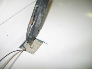
 

Drill a 3/16″  hole  horizontal below the Longerons, into the foam below the upper skin.  Fish the wires though the hole. 

NOTE: 
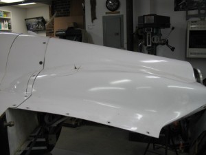
When I drilled the holes for the wires, I drilled from the cabin to the strake and was afraid I would drill into the tank.   Being careful, I angled the drill a bit too much and punched a small hole in the upper skin.  No big deal.  Better than drilling into the tank.   A little filler will make for an easily fix. 

Were I to do this again, I would drill from the hole into the cabin.   Just take some welding wire, flatten and sharpen the end into a flexible drill.  Insert your home made drill into the foam from the hole side and you can easily bore through the exterior and interior glass sides.  Using the pilot hole you can then follow it with a real drill from the cabin side….. NO CHANCE  of drilling into the fuel tank!!

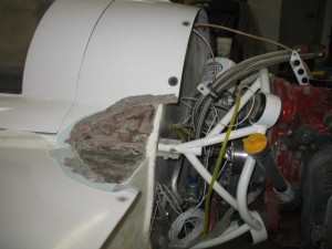
Lastly, use the razor knife to cut a square opening in the glass  inner skin of the strake for the probe tube.  The razor knife is used to prevent the possibility of  getting some chips into the tank which wound invariably happen if I had drilled a hole.   After you cut the 3 sides of the hole,  just bend the tab up and break it off….  no chips.
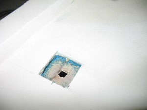
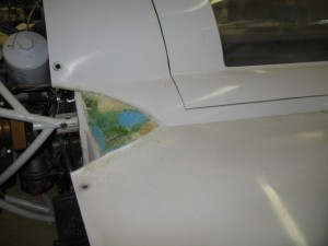
A nice hole, all sanded and ready for glassing.  Attach the wires to the probe.
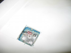
Mix some wet flox, and butter the bottom of the probe, install it into the tank and then fill the entire cavity with even wetter flox.  The probe/wires are completely encapsulated (potted) into the tank with wet flox…. did I say it is permanent?   In my mind there is no possible chance of fuel leakage. 
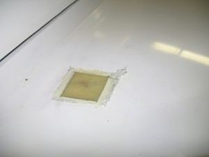
 

After a bit of reflection, I could see a few variation to an installation….

IF you DID NOT wish to immediately repaint, just cover the area around the hole (to protect your paint), cut the hole and install as shown.  When cured, remove the protective tape/paper for an unblemished paint job.   Make a painted Alum cover (like wing bolt covers) and RTV it over the probe hole.    Save the painting till later.

IF you wish to immediately repaint the area,  first mark the opening, take a sander and feather the micro back 1/2″, THEN cut the hole.   When floxing the probe incorporate 1 layer of BID in to the repair.    After curing cover the area with micro and sand every thing flush.  I doubt you would even have to put a second coat of micro on it.  Then paint. 

If  you are interested in purchasing the electronics call Grand Rapids Technology and ask for the Princeton CANARD capacitance electronics box.  Princeton is selling the CANARD module (with 5 calibration points) for $95 each .  

I am considering selling the probes for $40 each if anyone is interested.    You can easily make your own…  I did it.   I thought about detailing the construction of the probe, but decided against.  I know it is a few $$$, but I’ll be more confident they will work correctly for others if they are an exact copy of mine which has been tested.  By the time you buy the materials, have them shipped to you, machine the parts in a lathe, etc, it is not worth your time and expense.  I certainly wouldnt have gone though all this shit if I could have just bought a system off the shelf for a few bucks.

One afternoon while Todd and I were talking and trying to find a suitable name to order this specific electronics modification, Todd suggested calling them the “Nick Ugolini” electronics.  It is the name Todd jokingly gave them due to the frequently calls I made to get it working.     I thought it might be a bit to pretentious so I thought it best to decline…. 

Am I humble sort of guy or what?

What?
Apr 01 2010

Instument Panel Graphics

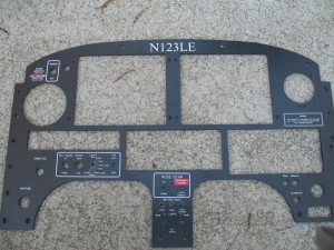
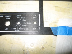
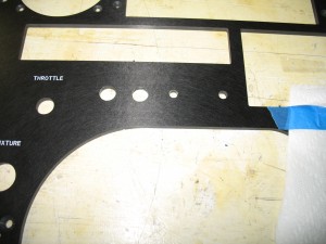
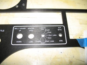
The instrument panel is now lettered.  It was ABSOLUTELY the most frustrating work I have done on the plane so far.  I spent tons of time messing with it and a few calls to tech support figuring out how to use the lettering system from Pulsar Pro FX .

When I first started, I only had about a 10% success rate after many hours or trial and errors.  After I re-reading the instructions a few times and changing my techniques, the success when up to about 60%.  A LOT more failures and I finally figured out how to make it work which was not covered in the instructions (and I surprised tech support with what I was doing) and now I am almost 100% successful.  What a PITA but it is finally done!

After lettered everything and getting it ready for shipment, my tape accidentally touched part of the graphics and removed the boarder!  Fu** 

So I made a new image and removed the damaged one and replaced it in about 15 minutes.  Cool!

The new graphic is in place!

I am going to try some clear spray sealer on a few test pieces to check the results of some abrasive tests.  I want to make sure the graphics are preserved until they get completely sealed in clear coat.

Mar 18 2010

In the shop again

After the trip to CA, I was really messed up for a last few days.  I was extremely tired (time zone/daylight saving changes) when I got back,  the back was bothering  and the after affects of the dental work all hit me at the same time.  Ouch!   The trip to LA was just exhausting in many ways and I was sure glad to be sleeping in my own bed again.   I guess a bunch of factors all hitting at the same time just caused me want to relax since my head just wasn’t into the game.   I needed to do a lot of thinking and reflecting.     Thank goodness for good friends to bounce ideas off of.  Felt like doing absolutely nothing on the plane….

Today, I finally started feeling perky again, physically and mentally and decided to get back to work.  I want to get this bird out of the shop, so Pat can enjoy it.   He will really love the great flying characterists of canards.  What a great community too.

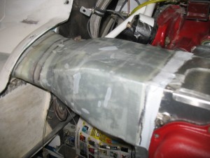
Before the CA trip the inlet ducts were glassed.  You can see the AL ring installed in the duct work of the STBD side to clamp the flex hose on after assembly.

The port side after glassing.  There is much more room to work with on the port side than the stbd side.   It is made a bit more bulky to allow the oil dip stick will penetrate this inlet duct.

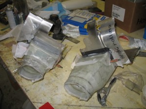
After removing all the foam and glass and cutting them free I found I could get them on/off the engine with forward baffles installed!  Great now I can rivet the inlets to the Al air boxes instead of screwing them on as originally planned (it will look and perform much better).    Some more glass work is necessary for fine tuning and I’ll be done with them.

Mar 01 2010

Cooling Intets

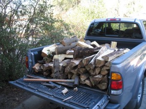
On Sunday, I had a great day after church cutting up a downed tree and hand splitting the wood.  Actually it was a lot of fun using an ax instead of a log splitter.   A bit of work but great exercise. 


  I have shifted directions on the down draft cooling system.  After carefully looking at the cowl, Pat and I decided that the reduction of the height above the cylinder (due to the DD cooling plenums) did not warrant chopping up a beautiful cowl.  If I had not cowl it would be a different story.    Overall, I would save a considerable amount of time by keep the cowls a close to original as possible.  The first step is to reattach part of the original fairing. 


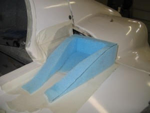
Foam was bonded to the inlets, shaped for glassing. 


There is an Alum ring (which you will see later which will be used as a support for a silicon vibration isolation tube.   The inlets both have about 12 sq in per side.   It should be plenty for cooling as it is about the same as my plane and my cooling works exceedingly well. 


Tomorrow, I will reshape this area, and start working on the inlet tube to the engine.   I feel shaping of the inlets is the hardest part of the down draft cooling.  The rest of the work is very simple.

Feb 01 2010

Still Baffled

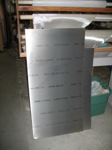
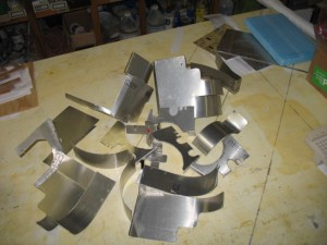
Want to know how to change a nice new 2 ft x4 ft sheet of Aluminum

To a pile of beautifully cut and formed scrap pieces? 
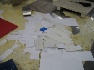
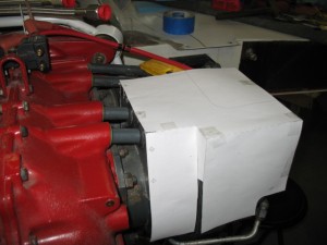
All you have to do is to cut a pile of scrap pieces of paper and spend a LOTS of of time prototyping an entirely new down draft cooling design…..


I have spend the last few weeks trying to develop a down draft cooling system totally out of aluminum….  Why you ask.  Well if you think of production costs, it is much cheaper to make stuff out of aluminum then fiberglass.  Just look at the cost of RV parts.  They are really inexpensive when compared to fiberglass, hand molded parts.  Machines automate the manufacturing process. 

When I started assembling a DD system (change from updraft cooling), I felt the project needed to be modeling in Acad.   Faster than manually drawing lines on paper.  

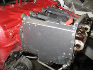
Then I got a bug up my b*** and it became a real challenge after I hit on a really simple way to seal the engine.  Using seals around the push rod tube.   They were very difficult to get right but they work!  The tube baffle has grommets for the spark plug wires and fuel injection tube.  These seals proved to be the key for the box design.  Normally, the only hard part of sealing the engine for DD cooling is the case.  As far as the cylinders, they are all the same and there are no variations.   So why not just seal what you really need to seal.  

Overall, the purpose of this exercise is to to eventually design a kit of precut/bent parts which could be waterjet cut in mass, sold cheap, which allows a builder to assemble a VERY TIGHT down draft box and reduce plane cowl height.  Never been done for a canard aircraft.    What, we could actually have a something manufactured for our EZ’s which is cheap?  Who would have thought….    The kit is applicable to a 320 or a 360, pusher/tracker setup (I think it would be great for an RV).    RV’s could get rid of that red silicon seal material. 

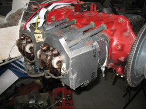
What I like most is when the builder is trying to balance the cooling on the engine, you only have two cylinders to work (the box only covers two cylinders on each side) with and since the cylinders furthest from the inlet are the coldest, it is very easy to block the box at the half way point to raise the temperatures of the remaining cylinder.

I went though a number of different designs…..

Design #1


Design #2

Design #3

Many different tube seal designs, lots of paper prototype parts

Design #4

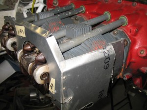
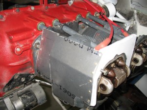
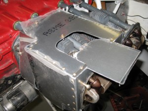
Finally, got it!  Here is the final design (the Al still it has the protective plastic on the metal).  Late after the cowl is finished, the plastic will be removed.

There is a sliding hatch held on with one screw which allows easy access to the spark plugs. 

All the parts just seem to majicly lock together almost like a chinese puzzle with a minimum part count.  Sometimes I even amaze myself!    Now the parts can be mass cut with a waterjet machine which means the kits will be very cheap and easy to reproduce. 

If nothing else and they are never manufactured, when I get around to modifying my other planes for DD cooling I’ll be able to make the DD cooling box in a day.    I’ll finish assembly of the box tomorrow.

Jan 20 2010

Cylinder Baffling

Work continues on the down draft conversion.  I am making the lower part of the DD cooling system in aluminum and the curves and upper part will be glass.  I am starting to realize with the close tolerances and difficulty of working with Al, that in the future, I would probably just make the head support in Al, and all the rest in glass.  It will be interesting to see after I am done if the effort is worthe the result, and which method might be the best in the future.  I’ll be doing this all over again for my cozy 4.  I must say, it does make for a nice clean installation ….

#1 Cylinder  

#2 Cylinder 

This is the brand new lycoming flow ported, high compression cylinder from Ly-Con.  Beautiful!  Unfortunately, Ly-Con sent 0-360 cylinder NOT 0-320 cylinder.  I feel it was totally their mistake, but we compromised on the shipping….  F***   Always something isnt there!

Received the in instrument panel test panel from the fabricator.  Overall it was GREAT!  All the instruments fit as planned with just a few minor adjustment on the holes.  I cant wait to see it populated and fit into the plane.

I also made a blended winglet test model to test out a new construction method I developed.  I want to put blended winglets on the plane.  I figured out a very quick way to build them that is self jigging, self leveling and leaves no possiblity of error or misalignment.  A complete coversion should take about two weeks.   Stay tuned for further developments.

Jan 13 2010

Cooling Inlet Design

Today was spent working on the cooling system inlet design.  After making a few plugs I wasnt happy with, I turned to AutoCad to model it on paper before building.  It is so much easier when you can see exactly what you’ll end up with before you start.  I really do need to start learning 3D model.  It would make my life much easier.

Initially I started out with a few hot wire cut pieces.

Pat was happy with this design, but I was not.    I am not comfortable with a funky NACA scoop instead of the tried and true ram air inlet.   The current plan is to first make a ram air inlet, then add the ramps (so Pat is happy) and if things don’t work out, I’ll have a fall back position.  Chop off the ramps and I am back to ram air!

This is a pdf file of the cowl design/cooling system design I came up with.  It is as tight to the engine as I could make it (1/2″ clearences over the spark plugs and plentum box).   

cowl design  1

Tomorrow, I’ll glass the inlet tube I made, then start working on the ducts.  Much to do, much to learn.

Jan 11 2010

Change in Direction

I have changed direction a bit.  I was working toward updraft cooling with this plane.   I have decided to working on downdraft cooling.  It will keep me busy for a month or two….  oh well, what else would I be doing…maybe retire?

Today was spent cutting and cleaning up of the strakes and planning for the down draft conversion.

I also stopped by Tony’s house to check out his work on DD cooling.  Funny, a few months ago, I was trying to convince Tony to use DD cooling and gave him a bunch of ideas, now I am checking out his work for ideas.   He is a terrific builder so it was interesting to talk about his techniques and experiences. .

Jan 09 2010

A New Year

It is the beginning of a new year. 2010. How does one say that these days? Is it ” Two Thousand Ten” or is it  “Twenty Ten” ?

My pronouncement would be Twenty Ten, since the only reason we called the 20th decade as ” TWO THOUSAND AND ##” is because of the movie “2001, A Space Odyssey”. The naming of the movie influenced the entire next decade of yearly naming conventions.  Can you imagine calling 2004 a “twenty oh four”.   No, it is only because of this movie this decade was different.

Well, I am finally back to work on the plane. The last time I physically worked on the plane was on 27 Nov.  For the month of Dec, I worked exclusively on the wiring diagrams of the plane.  When I finished on 30 Dec, I had put in 132 hrs of drafting time.   That’s about 25 hr with the holidays.  I ended up with 35 pages of drawings and a half completed spreadsheet (it will be filled in as I wire the plane).

I decided to document the wiring in a similar way to my Toyota Truck Wiring Book is written. The drawings are broken down by systems like charging, starting, lights, com panel, etc.  

This way if there is a problem with something electrical, it will be very easy to trouble shoot JUST that system. A light doesn’t work, it will be easy to see at a glance the entire lighting system without trying to dig out the wires of interest amongst other unrelated wire on a schematic.  It is a MAJOR PITA to document everything this way and a little more difficult to wire but the effort was definitely worth it.

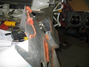
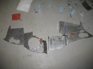
Now that the really hard part is done, the wiring plan, I can start back on finishing the things necessary to get me to the point of wiring. The engine is next. I want composite baffles on the plane instead of the aluminum type for more ridge baffles and better sealing of the cooling air. The currently installed baffles have massive air leaks around the perimeter.

Lots of red RTV is on the old baffles.

Composite baffles are more time consuming to make, but the advantages are perfect sealing of the engine, no cracking and you can do compound curved to attach the flexible baffles to. The extra effort creates is the best possible seal. We need the best possible cooling for the extra HP this engine is going to generate (estimated at 195 hp from a IO-320).  The baffles will look a little strange, as it will be comprised of both composite and fiberglass but it is best to match each material to it’s unique physical properties.

Here is the bottom engine baffles.   

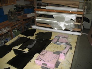
They were re-imagined in composites.  The form is foam and the glass is lay-ed out in order of use.

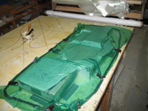
The part is vacuumed down to the table after coating with epoxy. 

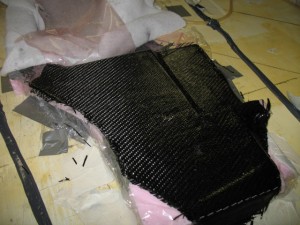
Carbon sure does look good when you are done and uncover your work.   I’ll uncover the rest of the part tomorrow after the epoxy has had a chance to get a little harder.