Category: LongEZ Upgrade

Nov 05 2012

Make your own MIL SPEC teflon wire strippers

I love to wire airplane. To properly wire, you must have the CORRECT tools for wiring.

One of the MOST important tools I have is my wire strippers. Why, because the wire we use in airplanes is VERY small, generally #20 or #22 wire and if you use the wrong stripper you can tear off the fragile wires of the core and reduce the current handling capacity of the wire.

YOU SHOULD NEVER USE ANYTHING OTHER THAN A MIL SPEC WIRE STRIPPER. NEVER

Two years ago, I bought a really Snap On teflon wire stripper at an airshow which cost me a whopping $200. The reason I paid so much is for this one reason…

wpid-CIMG1603-2012-11-5-11-002.jpg

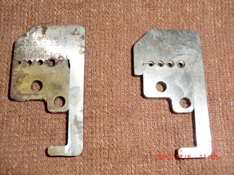
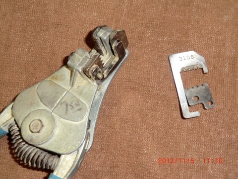
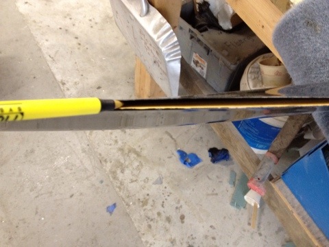
These little puppies. The blades. The one on the left is the standard blade you’ll find in tool boxes. The one on the right is a MIL spec blade found in the MIL SPEC stripper you should be using on aviation wire. The main difference is HOW it strips the wire. Almost everyone I have talked to don’t know the difference between a regular wire strip and the Mil Spec stripper.

If you look closely at the blade of the “non-approved” stripper it has VERY sharp teeth which cuts the insolation and many times the wires themselves. There is only 16 threads of wire in the small gauge wire, and if you lose 2 or 4 of them, you reduce the current capacity of the wire and weaken the termination point.

wpid-CIMG1605-2012-11-5-11-002.jpg

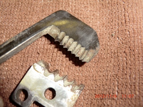
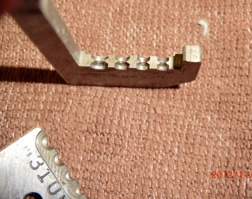
The MIL SPEC blades basically grip the insolation and tear it off. The wire openings have nothing shape on them to cut into the wire at all so you never cut the individual wires, you end up burnishing the wire bundle.

wpid-CIMG1606-2012-11-5-11-002.jpg

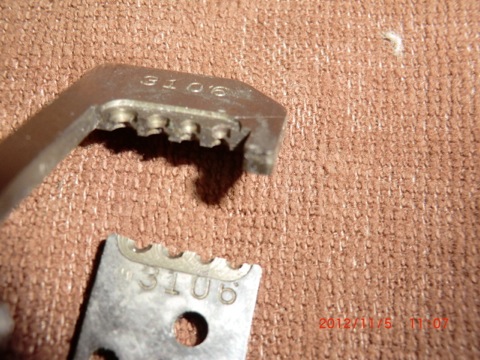
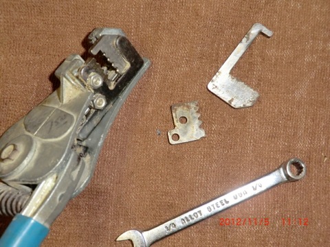
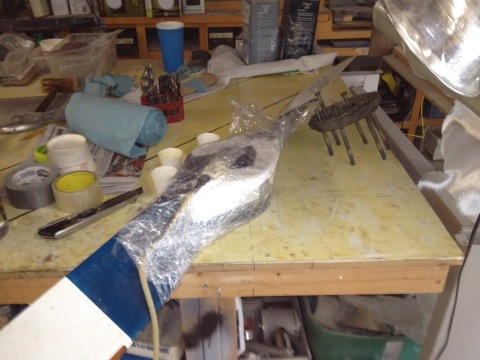
This is a better view of the inside of the blades.

wpid-CIMG1611-2012-11-5-11-002.jpg

I happened to have an old stripper (with the sharp cutting blades) laying around I picked up somewhere for $7.50. I remembered that I had and some replacement blades sitting around for 10 years which I bought at the Sun-N-Fun
“Fly-Mart” for about $15 but had never opened the package. I didn’t realize they were actually worth about $84 when I looked them up on line. So I thought why not use them.

To make your own professional stripper, just order the blades of your choice, and replace the sharp ones

wpid-CIMG1612-2012-11-5-11-002.jpg

with the MIL SPEC blades and save yourself over $100. It took me less than 5 minutes.

wpid-CIMG1613-2012-11-5-11-002.jpg

The stripper on the the left is my $200 Snap-On, the one on the right is the $22.50 stripper with the same blades that I put together from parts I had on hand.

wpid-CIMG1616-2012-11-5-11-002.jpg

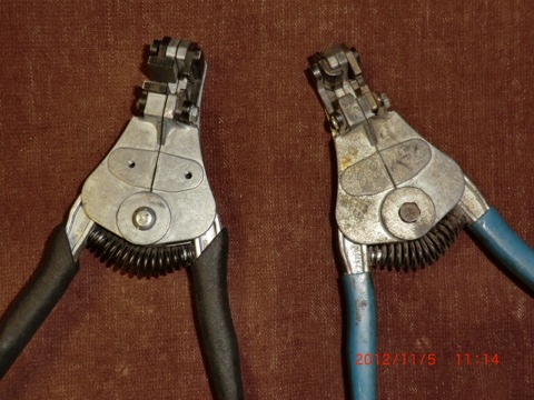
If you want to save some $$$ just find an old Ideal wire stripper (for the frame) and order the PROPER Mil Spec blades on line.

You can see the different type blades for the Ideal Wire Stripper here.

The L-5363 blade I installed which is good for for #16-26 Teflon wire can be ordered for $84 from Stanley

This blade should will take care of most if not all your wiring needs on the plane. Enjoy.

Nov 04 2012

Fuel Readout Installation

Shortly after I received the replacement display module from Aircraft Extras for the fuel probes I wanted to test it right away. Low and behold, it had the same backlight issue the the first one I received.

CRAP, I thought that there has to be a reason both displays weren’t working properly. When I looked again at the wiring instructions I found a small jumper wire had not been installed to power the back light. Apparently, the first unit I received was working properly and it was my wiring mistake that caused the first one not to work. Immediately, I sent an e-mail to the designer apologizing for my mistake.

Since I had already pre-wired the plane, installing the electronics interface with the display was a quick operation.

wpid-CIMG1529-2012-11-4-16-311.jpg

installing the unit readout in the dash was also very easy as I already had a hole in it which had been used for the TRIO altitude hold system that I BETA tested. The hole was just there, not being used anyway. The display was exactly the same type and size as the TRIO, so the replacement of the alt hold switch/display with the fuel switch/display was a perfect swap out.

wpid-CIMG1531-2012-11-4-16-311.jpg

Now the bird has a nice little lighted display, that has 6 input, can easily be programed with different screens, low/high level alarms and can be installed in any EZ, old or new.

The fuel probes with this display is a perfect combination for canard flyers who wish to have electronic fuel probes and have not rewired their planes for the latest glass EFIS panels or electronic engine monitors.

wpid-CIMG1592-2012-11-4-16-31.jpg

FInally, after years of dreaming and working with 2 different companies to develop my system, it is now installed and working in my plane. Cant wait to calibrate the readouts and fly with it.

Oct 29 2012

Makeing a Wobble Tester

This is a potential damage which could occur if you lose an exhaust valve. This is what is left of the head which was on my plane which caused me to do an emergency landing at Summerville Airport. I ended up with a cracked crank and had to do a complete engine overhaul.

wpid-P5090108-2012-10-29-16-181.jpg

The valve head broke off due to excessive clearance of the valve guide to the valve stem.

wpid-CIMG1577-2012-10-29-16-18.jpg

I decided to build the wobble tester, and check my valve clearances before I put the overhauled hydraulic lifters in. It took me a few hours I get a design I was happy with in AutoCAD. Actually making the tester only took me about two hours to build. The design is a bit different than the factory model as I mounted the dial indicator from the top down, between the rocker rod support columns (on the top part) which is opposite to the normal mounting (from the bottom up) which would require me to take off the exhaust system to test the wobble.

It allows me complete the test and not removed the exhaust system to do the testing.

wpid-CIMG1579-2012-10-29-16-18.jpg

The final result is made out of 1/2” aluminum plate.

wpid-CIMG1581-2012-10-29-16-18.jpg

Here it is being used on an old cylinder I had in the shop. Yah! I’ll be able to test the cylinders every year now to see how quickly the exhaust guides wear.

wpid-CIMG1584-2012-10-29-16-18.jpg

Oct 27 2012

Fuel Readout Frustrations

Today was a frustrating evening of my own making. Friday, UPS delivered my updated PMag (electronic ignition system) and a very interesting electronic readout from Aircraft Extras which will be used for my fuel probe system.

The PMag’s were tested and upgraded and they found there was NO problem with their operation, so they were not a factor in the vibration issue.

The Aircraft Extras electronic programable display is very cool. It is a tiny display (1”x1”)with the ability to monitor 6 inputs. It be using it to monitor Left and Right fuel level, the main and standby batteries, voltage output of the MAP ( the manifold pressure sensor) which according to Klaus is the best way to monitor power output when used for drag reduction testing and one left over for a spare which I’ll eventually hook up to something to be decided later..? I think after I finish with drag reduction, I’ll connect #5 and #6 inputs to the fuel probes too. This way one can not only get fuel display (my primary use), but I can also use #5,6 to display a RED flashing screen to display LOW FUEL. If that doesn’t get my attention, nothing will! This little display and monitor anything with a voltage output and has LOTS of different display screens to chose from. I may use it to monitor belly board position, oil pressure or ??

wpid-FuelGauge-300-2012-10-27-20-58.jpg wpid-PastedGraphic-2012-10-27-20-582.tiff

A very small system. I only wish it could monitor more inputs (like 16 or 24) instead of just 6. It could be used to monitor anything electrical in the plane. Very cool little device.

wpid-PastedGraphic3-2012-10-27-20-582.tiff wpid-PastedGraphic2-2012-10-27-20-582.tiff wpid-PastedGraphic1-2012-10-27-20-582.tiff

Naturally, after receiving the AG6, I wanted to test it at home, get comfortable with the programing and operation before installing it in the plane. Ended staying up past midnight last night messing with the display to set it up for my needs. The AG6 VERY easy to configure and program once you get past how the software programing functions.

wpid-CIMG1567-2012-10-27-20-58.jpg

Low and behold I couldn’t get it to work quite like it should. I could tell it was alarming and functioning but there was no backlight color when it was alarmed. A red flashing display is very important to me for the intended use in the plane. The Princeton electronics in the test cell fuel calibrated and worked perfectly but not the readout.

wpid-CIMG1570-2012-10-27-20-58.jpg

This morning it was up early for more testing, more calls to the designer and finally sending him the data settings for evaluation.

Overall it is my goal is to develop a small, complete package of a fuel probe and a readout system for those canard flyers who don’t, won’t, or can’t upgrade their planes to latest Glass Panel type displays. Something that can be easily installed in any canard even if one has very limited panel space (like my plane).

Overall, this is no different from developmental pains of designing the probes. It took almost a year of going back and forth with Princeton Electronics to get the level sensing electronics module working properly. I really like the small foot print of the readout and can’t wait to get it calibrated and working in the plane. It is just a matter of figuring out what is wrong with my setup. After the proper configuration for the fuel level alarms (1/4 tank, 1/8 tank) is determined, the designer will configured and saved the program file so when a canard owner buys one of his readouts for my probes, it will be pre-programed to my specifications so it can be used right out of the box with no fiddling.

After a morning of frustration, it was off to the airport to modify the instrument panel for the readout, wiring and mounting of the electronics which will ultimately occur when the display is working properly. I want to do as much tomorrow as I can as on Tuesday (after install my hydraulic lifters delivery on monday) as it is going to be COLD here (high in the 50’s) which is the result of the Hurricane Sandy which is moving through the area today.

NOTE: After returning the display and getting a new one, I found out that the original display was working perfectly and it was my fault the backlighting (alarms) were not working…. I DIDNT hook up a small jumper wire which powers the light of the display. No backlight power, no colored alarms! Sometimes I am amazed at my ability to frustrate myself.

After reviewing the installation instructions I found my mistake, hooked up the jumper and all the backlight functions of the display worked as designed. The good part of the story is I found the designer was very helpful at trying to solve my self induced problem, and I learned a lot about how to use and program the display.

Watched 3 episodes of a new show on CW called “Arrow”. It is taken from the comics and is about a man who is fighting crime in the city with a bow and Arrow. Sort of like batman with a bow. Actually, it is nicely done.

Nov 01 2011

Piston Upgrade

The engine work was fairly easy to do but again took a bit longer than the 1.5 days I expected (took 2.5 days). I ran into a few issues such as properly honing the cylinders and the cylinder wrench which would not work with the wings installed on the bird. I had originally built up the engine in the shop with the wings removed and plenty of room to work.

The wrench came home, I cut about 4 ” out of the length and rewelded it. I was a bit concerned because of the 50 ft lbs of torque used to tighten the cylinder nuts. It worked just fine welded up.
20111106-115950.jpg

Day one was spent getting a hone, welding the tool and replacing #2, #4 pistons. Day two was spent putting the baffles on the stbd bank, removed port baffles, and replacing the remaining pistons.

This picture shows the removal of #3 cylinder and baffles. I was amazed at to how obstructive the oil cooler is in the engine compartment. It really gets in the way of engine work. I cant wait to move it out the the wing as I did with Pat’s bird.

20111106-120018.jpg

The cylinders were honed on the table with a cheap ass AutoZone honer. I had a really good one from Tony, but I didnt want to possibly affect the size of the cylinders. His hone was not the right type for a closed type cylinder.

I checked out the stores for a dingle berry type, but they were $179 and not in stock. Found a 3 bladed type hone at AutoZone for $31. For lubricant I used diesel fuel which was recommended with the hone Tony owned. The diesel lubricant worked surprisingly well and really helped cut the glaze better than using it dry.

20111106-120114.jpg

I also talked to Klaus (Lightspeed Engineering) about timing changes needed when going from 7:1 to 9.1:1 pistons. He recommended retarding the time about 3 deg (to reduce engine CHT temps) and Pmag recommended retarding the time 5 deg. The Pmag only required a jumper to be installed, and Lightspeed required the removal of the flywheel to make a slight mod on it. Hopefully the engine wont overheat due to the increased power output.

About 4 hrs more on the 3rd day to balance the prop/engine and work is done.

20111106-120202.jpg

I only ran into one serious issue. Since I was upgrading the engine (piston compression) which will raise my hp from 150 hp to 165-170+? hp the 150 hp prop no longer fits the plane. My brand new Hertzler prop had delaminations on the upper blade when I pulled it out of the storage box.

Gary Hertzler was very surprised and apologetic for the problem and had me send it back for refinishing. Gary’s support is really first class…. He is also going to upgrade the prop to the latest urethane leading edges he now installs on his props.

My 150hp Hertzler prop had his original LE protection which was easily eaten up by rain. While at Oshkosh one year, I found a manufacturer selling urethane which was designed for props. I ended up cutting Gary’s LE material off and installing a urethane LE using pressure injections (what a mess). Since then, I have flown through lots of rain with absolutely no effect to the prop (other and eating off the paint). When I first suggested the improvement to Gary, he jumped right on the suggestion, researched better materials and now has it on all the props be sells. You cant go wrong with a Hertzler prop.

20111106-120330.jpg

The seperation was almost 18″ long. Seperation is highly unusual and it is only a very few props were affected when Gary went to a new manufactring process (which has been improved).

Strangely, I found a few delams on my prop too due to heating by the exhause. A quick repair, a little micro and paint and it was read for balancing and test flight. Cant wait to get my new prop back to really see how the engine upgrade affects speed and fuel efficiency.

20111106-120524.jpg

Oct 26 2011

EZnoselift Installation

After I returned from Calif it took a few days to get my life back in order (as it always does when you are away for a while). Since I was planning to fly Tweedy up to PA for a birthday surprise on Nov 3 a goal was set of installing the noselift and higher compression pistons before I left Charleston. I wanted to have some steady run time to break in and seat the rings on the trip.

The noselift was a real challenge due to existing wiring and an electric panel which required relocating. The work took a few days longer than I would have hoped for, but in the end result it was worth the effort. Jack Wilhelmson gave me some excellent support for a few wiring questions and it worked great from the first power up.

Here is just the beginning of the disassembly. Most of the electrics in the nose had to be removed and relocated. It ended up the 32 ahr battery had to be replaced with a smaller 18 aHr Odyssey battery due to space issues. I found the best price on the battery from Amazon which was almost $40 cheaper than ACS with free shipping! The battery change was actually helpful since the noselift weight about 8 lbs more than stock and the smaller battery compensates for the weight increase in the nose. The weight of the plane actually went down a few lbs and my CG didn’t change a bit.

20111106-110212.jpg

I had to remove the old Dr. Curtis ratchet handle he used to sell. It worked great for 12 years.

20111106-110304.jpg

After the old system was removed, a nice paint job covered everything up. Surprisingly I didnt have to do anything to the panel other than remove the handle, sand it flush, paint and bond on the new electric panel. Glad something what easy on this install.

20111106-110321.jpg

The wiring was easy to do and looks much better than my old 12 yrs inexperienced wiring job.

20111106-110355.jpg

More wiring

20111106-110628.jpg

Finished. Looking forward to testing the automatic extension system. It is also nice to be able to park the plane in the half way down position to move it around the hangar.

20111106-110418.jpg

Next step pistons for the engine.

Sep 28 2011

Two Days left to go

These last few weeks have been absolutely crazy for me.  I am leaving for our annual Rough River flyin in this weekend (Friday morning) and only have two days left to go.  Seems like I been doing a million things at once to try and prepare to leave.  Lots of little squaks on the plane lots to do around the house.

Later when I get back from California I will detail the work I did on the plane and catch up on the past enteries in my blog.  Here is a few things of interest for you…

I installed an “In the wing oil cooler” which is working really well.   The oil temp is now between 190-200 f at any power level.    Before I installed it I tested various locations while flying.

I also tested foam samples for heat damage prior to starting the project.

I really like the fact that it is no longer in the engine compartment.

Cowl mods came out really well.  I extended the cowls 4 inches and built in some eductors.

The wing mods came out really well too.  The upper wing air flow is terrific the bottom is fairly well too.

Today I made an iPad knee board.  It has a hinge on the bottom and one on the side, so I can write on my paper pad (as as I am used to) and it flips to the side and the iPad tilts up and locks.  I think it is really cool… and suits what I really need for flying.  I couldnt find what I wanted from any vendor, making it was the only option I had….


Tomorrow will be be mainly dedicated to preparing for my flight out on Friday.  It will start my odyssey of the cross country trip…  How exciting!


Sep 14 2011

Ties downs

Today was for wrapping things up before I take the plane back to the airport for the final test flight prior to flying to California.

I machined a set of bushing to be floxed into the wings a guss locks for the rudders.  The pins have a little ball bearing in the ends to hold the pin in place when inserted into the tube.  Only thing left to do is to install them into the wing.

I also made some alerion locks for the wing.

This year was a tornado on Wed at the 2011 SNF event.  I was supposed to fly down there on Wed and am really glad that I didnt after seeing all the distruction and damaged planes.

While looking at the damage I happed to come across a big pile of broken “Claw” type tie downs which all failed in exactly the same place.  One thing which was really apparent was that ALL of them failed in exactly the same spot. It is a poor design made of inferior cast aluminum materials.    I have never liked the cork screw type of tie downs either..

I found a much better design called “Storm Force” tiedowns which I really like.  Check out this video

I made my own set for about $10 instead of $100.  All I need is a hammer and bag to complete the set.


Sep 13 2011

Oil Dipstick (updated)

As you may remember I had to move the oil dip stick filler tube outside my inlet plenum to accommodate a smoother flow of air into the engine trying to cool #3 cylinding.  I found a neat idea on the web for makiung a flexible filler tube (cutting the filler tube and using a piece of hose to join the pieces) and a dipstick made from a piece of vinyl coated cable and a custom machined cap.  So I made one.

The problem is you cant see the oil level (especially if it is new clear oil)..  I used some ferrals on the cable (top) to indicate oil level.  Problem is the ferrals got stuck in the tube and again was hard to read.  So I made a second cable (bottom)  with a tube swagged onto the cable.  The idea was to try and mimic the orginal level rod as much as possible to check the oil level.

When I took the oil pan off (to fix some leaks) I found the flexible cable to be really loose and floppy in the oil pan area.  There is no way to get an accurate reading of the oil with this type of system.   Humm…???

The second attempt cable is in the top picture and the updated cable/rod is on the bottom.  Basically I took the cable idea for the flexibility and a rigid tube for readability to make bendable tube/cable level rod ….  The secret to it is a spring near the cap which holds the ridge tubes in compression on the flexible cable.

This tends to keep the level rod perfectly straight off the plane and locks as straight as possible when mounted in the plane.

here you can see the three pieces of tubes bending on the cable.   This allows the level rod to negotiate the bend of the filler tube.

When  released it is perfectly straight.  When checking the cable/rod mounted in the the plane, I found it mimics the original solid dipstick in the oil pan area so now I’ll get accurate reading of the oil level.  Only thing left to do is calibrate it when I get the  oil pan on.

Sep 07 2011

Belly Beacon

Today’s effort was putting in the new belly beacon light and new dash panel knobs.

The Aero LED belly beacon is actually an interesting story.  At the 2010 Oshkosh airshow while taking to the owner of Aero LED I mentioned it would be nice to have a belly beacon which was also a strobe light.  The beacon would flash red (off/on) like a standard aircraft beacon, and the strobe would be synchronized with the wing strobes.  There is nothing like it on the market.  Apparently after the show Dean (the owner) decided to market the product, he designed it and at the the 2011 Oshkosh show, I purchased it and have now installed it.

This is the selected position for mounting the light

After checking the strobe on the fuselage I realized it is much too tall for my liking and I didnt like all that metal showing, so I decided to submerge it into the fuselage.

A cover plate was first constructed,

After cutting and sanding the opening, I only left about 1/16″ of the metal showing.

Here is how it looks from the inside.

After waxing and taping the light so the micro wouldnt stick, I micro’d the hole with the light in place for an exact fitting into the fuselage.  Next it was installing some hard points to mount the light.

Finally wiring and installation of the light cover.

In this case less is certainly more!  (more better looking)….

Lastly, wanted to change all the knobs so they would all look the same as the knobs on the Grand Rapids EFIS Panels.  So I ordered the knobs from GRT, made a bushing for some of the shafts due to their non-standard sizes and mounted them.

I think the change gives a more consistent look of the panel….