Pitot – Static System
Today the pitot/static system was completed.
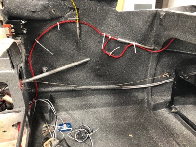
I have a bit of a different idea about plumbing the pitot/static system. I like to use .093 polyurethane 4mm tubing (yellow-static, red-pitot) for my instruments.
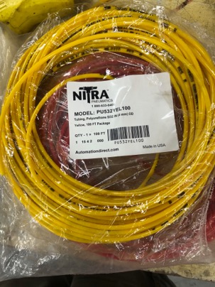
This tubing has a very small ID diameter and is very tough. Since there is no air flown in the static and pitot system one can use a very small tube to transmit the information. I think using 1/4” tubing for these system is way overkill and completely necessary.
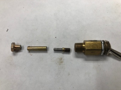
I have made adaptors to use with 1/8 NPT to 1/8 in tubing, but I found it easier to just by a 1/8” -2 flare fitting and machine the nipple down to .125”. Easy.
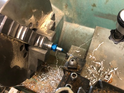
I found a deal on Ebay for 6 AN4-2 fitting for $15. Saved me a bunch of work and they look nice.
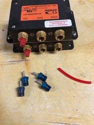
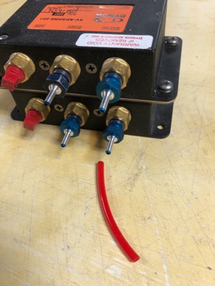
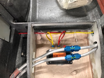
Installed in the AHARS.
A small adaptor had to be made for the alternate static air mechanical switch using a AN-3 bolt as stock.
I like using the different colored tubing as it make identification of the systems very easy. Here is the Pitot tubing in red.
The AHARS is plumbed.
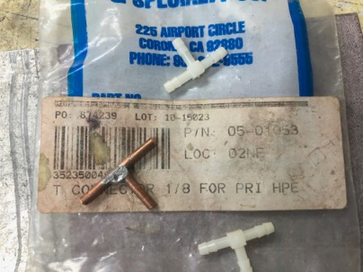
For the T-fittings, I used some 1/8” copper tubing and soldered a tube it. Very easy to make and very robust. The tubing is very hard to stretch over the 1/8” fittings and will never come off.
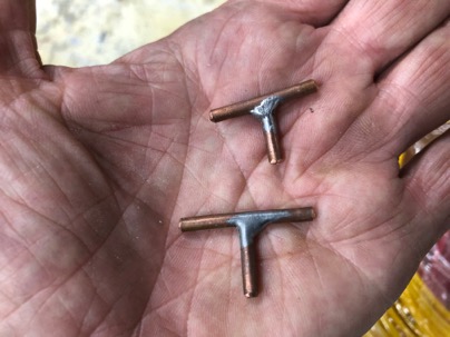
You can buy these nylon tee fitting from ACS PN 05-01053 but I found my home make ones work great too. The copper ones are a little heaver, but it is easier to install the tubing on them than the nylon one. If necessary you can heat the tubing up to stretch it over the fittings. It will shrink back done to tightly grip the fitting when it cools down.
 ’
’
![]() Uncategorized | Nick |
Uncategorized | Nick | ![]() Comments Off on Pitot – Static System
Comments Off on Pitot – Static System