Search: panel mounting

Apr 11 2016

Building Tips: Finish Mounting Cans

Now that you have determined the position

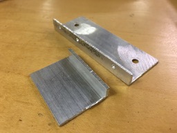
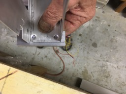
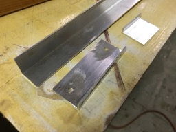
Next cut a piece of angle (thin, purchased at Home Depot) with the short bases the width of the separators in your panel.

UNADJUSTEDNONRAW_thumb_284c2-2016-04-11-18-30.jpg

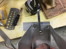
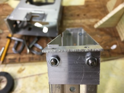
They will end up looking like this

UNADJUSTEDNONRAW_thumb_284c6-2016-04-11-18-30.jpg

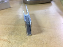
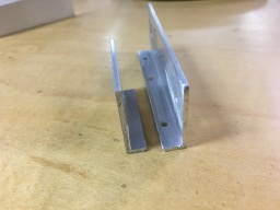
here you can see if you shorten one leg, they will nest on top of each other for a very narrow stack. In my case the separation between the radios is about 1/4”. In this case there is no way to use a screw and nut on the bracket to the radio can. It will have to be riveted.

UNADJUSTEDNONRAW_thumb_284c7-2016-04-11-18-30.jpg UNADJUSTEDNONRAW_thumb_284c8-2016-04-11-18-30.jpg

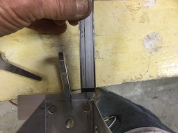
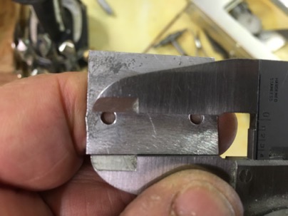
Using the hole location on bracket calculated, mark a line on the bracket,

UNADJUSTEDNONRAW_thumb_284ce-2016-04-11-18-30.jpg

verify the location

UNADJUSTEDNONRAW_thumb_284cb-2016-04-11-18-30.jpg

insure it is square, mark, remove the bracket and rivet it to the can.

UNADJUSTEDNONRAW_thumb_284cc-2016-04-11-18-30.jpg

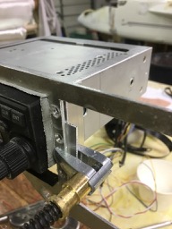
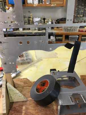
once it is the bracket is riveted to the can, you can clamp the can to the instrument panel, Put some heavy duct tape around the hole and insert your instrument to center in the instrument panel. The duct tape will protect the finish of your instrument.

UNADJUSTEDNONRAW_thumb_284cf-2016-04-11-18-30.jpg

with the radio in place, clamp the bracket to the panel and drill the mounting holes.

UNADJUSTEDNONRAW_thumb_284d1-2016-04-11-18-30.jpg

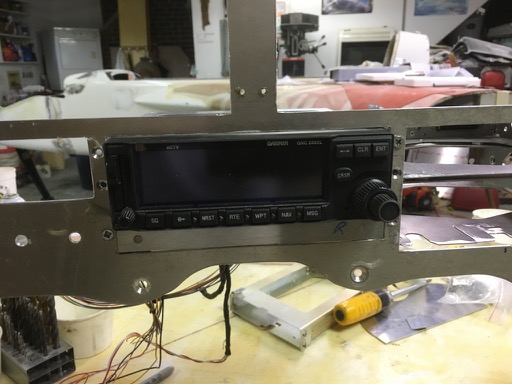
remove the can, install nut plates on the back side of the mounting brackets and reinstall. Then mount the can and check it out. Here you can see I added a strip of AL prior to drilling to simulate the mounting bracket which will be on the radio next to it since the brackets are nested together as shown above.

UNADJUSTEDNONRAW_thumb_284d0-2016-04-11-18-30.jpg

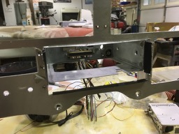
in my case, all instruments were level (perpendicular to the instrument panel) and within .010” of each other. A very easy install for a tight panel.

UNADJUSTEDNONRAW_thumb_284d3-2016-04-11-18-30.jpg

UNADJUSTEDNONRAW_thumb_284f1-2016-04-11-18-30.jpg

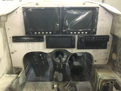
The final result. Nice….

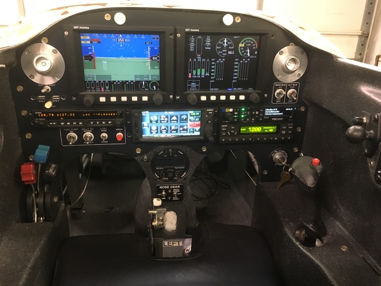
IMG_5033-2016-04-11-18-30-2.jpg

Apr 05 2016

Building Tips: Mounting Radio Cans

The first time I mounted my radio cans resulted in a terrible job. It is hard to hold the cans perfectly aligned (horizontally, vertically and angularly), mark the hole and drill it for screw/nut.

Here you can see how far my first attempt was off. At the end of the can (where the wires attach) it was about 3/4” off. I decided to throw them out and start anew with a little thought as to the best way to do it.

IMG_4303-2016-04-5-17-07.jpg

IMG_4308-2016-04-5-17-07.jpg

The issue really is you want to mount the cans with a certain amount of exposure so all the cans stick out exactly the same amount and the are perfectly level and straight behind the instrument panel. I dont feel using screws on the cans is the answer. Yes, you can file the holes and make adjustments, but you CAN NOT do that if the radios are really close set. My radios are 3/8” distance apart. I can’t even rivet braces to the front panel and use nut plates and screws.

Here is the method I successfully used.

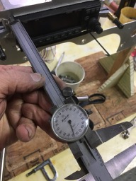
You’ll need a dial veneer caliper, Gorilla tape (nice and thick at .025”) , Alum angle (from Home depot), screws, nut plates and rivets.

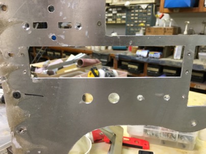
File the top of your can hole and one side straight as reference lines. Using these sides as a references, file as needed the two remaining sides till the opening is about .040” bigger than your radio face plate.

IMG_4305-2016-04-5-17-07.jpg

Put strips of the gorilla tape on the edges of the holes. This will not only protect the expensive finish of the radio, but center the radio in the opening. File the hole till the radio fits nice and snug.

Drill holes in the instrument panel where you intend to put the mounting screws. I used a #XX drill for the clecos. I like to drill a minimum of 2 holes per radio or for a stack of radios I drill 3 holes.

IMG_4302-2016-04-5-17-07.jpg

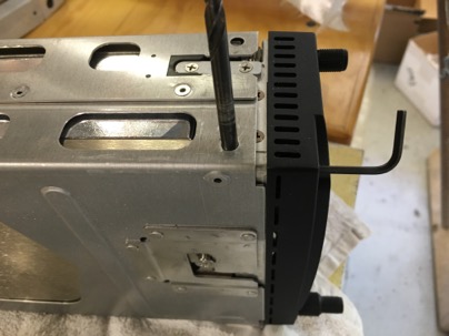
Next stick a drill bit in the hole to measure the diameter of the hole.

IMG_4306-2016-04-5-17-07.jpg

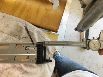
Measure the distance from the face to the edge of the drill bit

IMG_4307-2016-04-5-17-07.jpg

Now decide on the amount of exposure you want on the radio. In my case I wanted .050” because my GRT EFIS has a 1/2” exposure.

Because of my narrow openings I had to stack the support brackets.

Location to drill the bracket rivet holes = (Exposure desired + panel thickness) – ((Hole dia/2) + distance from face to edge of hole)

For my Garmin GTR200 it is: (1/2” exposure + .090” panel) – ((.198” drill dia/2) + 1.088” from face of radio to edge of hole) = .597” distance from back of panel to center of the mounting hole

A quick spreadsheet and it is easy to determine the exact location of all the bracket mounting holes.

ScreenShot2016-04-11at5.29.05PM-2016-04-5-17-07.png

Now it is time to mount the brackets on the cans.

Apr 04 2016

Building Tips: Design/cutting an instrument panel

I have built a couple of instrument for canard aircraft and it is always a challenge. Especially for a LongEZ since panel space is a premium and the spacing between the radios.. Here are a few tips to help you with the process.

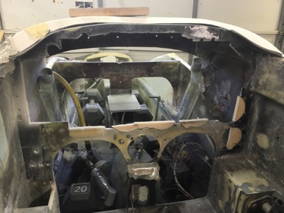
Here you can see where I created a space for the new instrument panel I had to plug a few instrument areas and mounted nut plates on the backside of the perimeter of the old panel. These nut plate will help you index the new panel templates.
IMG_4205-2016-04-4-10-54.jpg

I like using .090” 67061-T6 aluminum. It is easy to machine, stiff enough for the purpose and most importantly, most set backs (exposure ring) of the instruments is designed for a panel of this thickness. You’ll also need a basic computer drafting program (I use Auto-cad) which helps with the design of the panel and some basic hand tools such as a jig saw, drill, rotary grinder and band saw. That it!

Initially I start with a rough measurement of the panel space to layout out the design of the panel. Don’t worry about the perimeter edges of the panel. That will be done later.

With your basic instrument panel layout on the computer done, get a 4×8 sheet of 1/4” luan ply wood. Cut and trim it to fit in the panel space of your plane. It is much easy to shape, sand and grind to fit perfectly the the AL is. Trying to model the permitter of the panel on the computer is very difficult because our planes are all custom built and a waste of time.
wpid-IMG_4397-2016-04-4-10-54.jpg

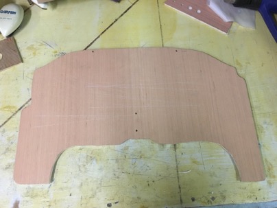
Next step is now that you have the basic panel made, you need to index it to the plane. On this picture you can see two holes at the top and middle of the panel. This panel becomes your your “Master Template”. Transfer drill the alignment holes to the mounting flange. DO not drill permitter mounting holes at this time.

The master template allows you to easily make more copies as needed and it will always fit. The index holes allows you to always place the panel in the same location. It was fairly mark the holes on auto cad, then print 8×11 sheets of paper and glue it to the panel and drill the holes. You never change these hole locations as you modify your drawings or make new panels.

Next. Trace your new panel onto another sheet of luan, cut it out and drill it for your first working copy.

Now you finalize your instrument locations and test design. You can print out individual sheets of paper and glue and tape them to the panel or if you have a wide printer you can make one LARGE printout and glue it to the working copy. I did it both ways and they are equally accurate. Here is the printout glued to the wood for a first look at the layout.
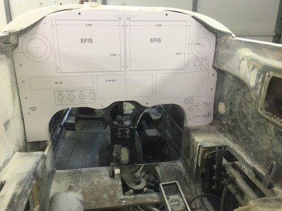
wpid-IMG_4228-2016-04-4-10-54.jpg

Hum, will the cans fit and was sort to problems to I have going on behind the panel? Yep, I had a number of unseen issues. With a bandsaw you can easily cut the working panel out in a minute or two since you aren’t worried about destroying your ‘working’ panel.
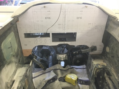
wpid-IMG_4220-2016-04-4-10-54.jpg

Here you can see I am not even worrying about the perimeter or strength. Just plunge cutting with the band saw to open the holes up. You end up with a panel that has no real structural strength, but will allow you check the fit and feel with the cans lightly placed. LOTS of issues with my first draft.
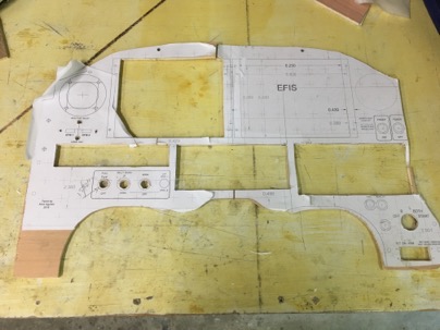
wpid-IMG_4402-2016-04-4-10-54.jpg

This is the panel pasted together with individual pieces of paper. No strength, just hacked and cobbled together.

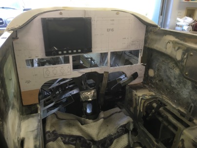
Mount the panel and test fit your instruments.
wpid-IMG_4222-2016-04-4-10-54.jpg

wpid-IMG_4230-2016-04-4-10-54.jpg

Now you have a good idea of interferences and problem areas. I needed to make all sorts of adjustments… such as switch location and vent locations (too high)…first iteration done. Back to the computer for to modify the drawing.

Throw this copy of the panel away, use your ‘master’ and make another copy of the panel as it only takes a couple of minutes to cut it out on the band saw.

Glue your updated paper templates to the new working panel, cut it out …this time I used a jig saw for a nicer panel to see if the radios were a better fit after being moved and they were. Now that I am reasonably happy with the layout, I used this wood copy to drill the perimeter mounting holes in the working copy and transferred them back to the master copy. Use the master copy to NOW drill the permitter holes.

Taking your ‘master panel’, you can trace it onto the aluminum panel and cut out. Transfer drill you holes into the AL. Now place the AL panel in the plane and using the holes as guides, drill all the holes around the perimeter of the panel into the mounting flange. Make your nut planes and flox them on to your mounting flange with screw through the panel. You now have your master panel cut in AL. Now you want to check your switch locations and any other problem areas before cutting up your nice Al work.

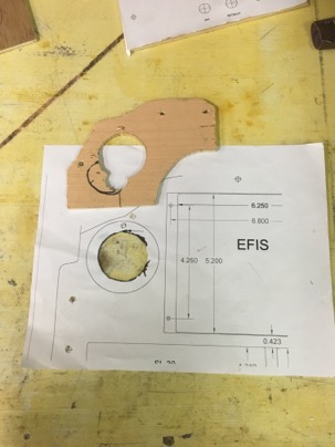
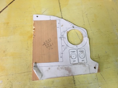
NOTE: What is cool about making your panel this way is you can quickly fine tune small sections of the panel. I was a bit unsure of exact locations of the vents opening (due to backside mountings nut plates and switch locations. You can quickly make test panels to how it works for you.

To check your locations, print out that section of the panel on a piece of paper, glue it to a scrap piece of wood, trim it if necessary, and transfer the mounting holes from the master panel to your working panel then test it.
wpid-IMG_4407-2016-04-4-10-54.jpg

wpid-IMG_4403-2016-04-4-10-54.jpg

Had to move the vent holes slight down.
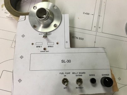
wpid-IMG_4277-2016-04-4-10-54.jpg

Testing the switch distances and heights. Again, more adjustments….

You get the idea, I must have made half a dozen small test panels moving the instruments/switches,/holes slightly up, over, and apart, testing and looking and then correcting the locations on the computer. It is a terrific way of making sure the work you invest making your panel will work fit and be right the first time. Once and done.

This sounds like a bit of effort, but trust me, you dont want to make a mistake on a CNC cut panel because your switches are too close together, or you have some other crazy interference problem. It was very quick to to make the small test sections and test them.

Now you have a final design on the computer but there is just one more step needed prior to cutting it out.

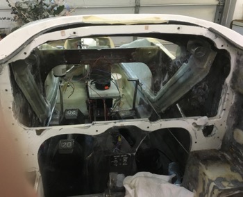
When you mount the blank AL panel and check it with a straight edge, you will find it will probably be twisted slight but it definitely won’t be straight and flat due to the way the flange was installed. You will need to ‘bed’ the panel to make sure it stay straight when all the holes are cut out.

Wax the back of the aluminum, take some WET micro, put a small amount around the permitter and mounting holes, remount the panel and lightly fighting the screws to pull the panel down. Use a straight edge to make sure you pull it flat and straight squishing out the micro and let it cure. In some areas I had to use pieces of wood stir sticks to act as shims until the micro cured. The panel is now bedded and completely flat when the mounting screws are tightened. Yah!!
wpid-IMG_4400-2016-04-4-10-54.jpg

NOW you are now ready to cut the panel out. I think you can do it a number of ways. CNC, using a mill, or a jig saw (my choice). For this panel I used the jig saw first, then cleaned up the lines with a mill. Mostly the mill work was a waste of time.

The paper template protects the AL, and using a jig saw with a light touch will result in amazing straight lines. Center punch the holes for the switches and use a rotary grinder to open up the circles.

I ended up doing a lot of filing on openings anyway after I milled it to size them for the instruments (since each is slightly different), so milling the panel really wasn’t needed.
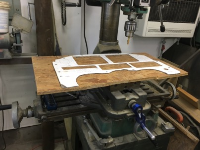
wpid-IMG_4287-2016-04-4-10-54.jpg

here you can see where I drilled the round holes with a lot of small holes to allow me to use the jig saw to open the circle up. Then using a air grinder with a rotary bit allowed for a reasonable accurate circle, then a 1/2 round final was used. A perfect hole for sure and overall, it took very little time to do. A sharp file cuts this grade of aluminum very quickly.
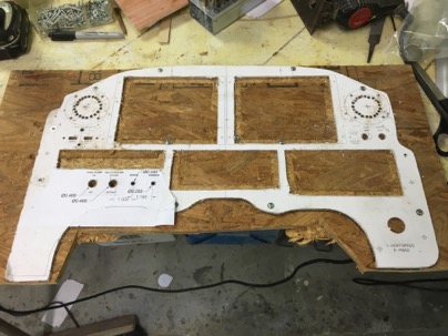
wpid-IMG_4288-2016-04-4-10-54.jpg

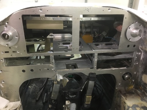
The panel is cut and ready to mount the radio cans. The cans presented a special problem due to the narrowness of the opening between the radios (3/8”). My first attempt to mount the cans turned out to be total crap as all the cans were not level nor straight and wiggled around a bit.

I threw the mounts out, spent some time thinking through the problems and came up with a much better mounting solution which resulted in the vertical alignment at the far end of the cans within 1/16” and the exact desired setback of all the radios to within .500” (+/- .25”) to match my GTR EFIS face place. Straight and level. All the guess work was eliminated and now they are firmly mounted with no movement. Nice.

My next post will detail this technique.
Jun 26 2020

Installing the radio cans

Installing the radio cans is simple and straight forward, but it does require a little thought into what kind of presentation you would like to display.

Typically, radios are installed with the fascia of the radio on the surface of the panel. Trying to just drill holes in a side plate is harder than one might think because of alignment of each side, trying to be perpendicular to the face of the panel, and where the mounting holes are in the cans (the are all different).. I find this method unacceptable because additionally, each radio or piece of equipment has a different depth of its face which (to me) unintentionally makes the panel look a bit disorganized with each piece of equipment just sticking out into the cabin a different amount.

I prefer to recess the cans into the panel to provide the exact amount of exposure necessary so all radios and equipment have the same exposure height for a nice organized look.

Actually, I found a very easy and fast technique for installing the cans which also ensures all the cans are perfectly perpendicular to the face of the panel. Once you decide on the amount of radio exposure desired, use this method to mount the radio cans. This is post from April 2016 when I used the same method for mounting the cans in my LongEZ. http://nickugolini.com/blog/?s=panel+mounting

Personally, I prefer using rivets instead of screws to attaching the cans to the side brackets which prevents any movement of the cans

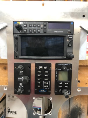
Radios in place to check for the look I want.

IMG_1476-2020-06-26-11-55.jpg

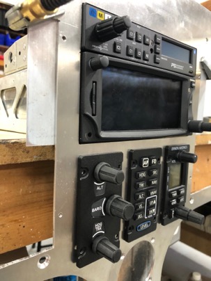
Normally the Garmin has a .850” exposure. The Audio panel had a .780” exposure which would be a .070” mismatch. The Dynon sub panels have a .150” exposure. Here you can see how far I have recessed the radios into the dash everything lines up perfectly. After installation, all the exposures were within .020” of each other.

IMG_1477-2020-06-26-11-55.jpg

Oct 27 2012

Fuel Readout Frustrations

Today was a frustrating evening of my own making. Friday, UPS delivered my updated PMag (electronic ignition system) and a very interesting electronic readout from Aircraft Extras which will be used for my fuel probe system.

The PMag’s were tested and upgraded and they found there was NO problem with their operation, so they were not a factor in the vibration issue.
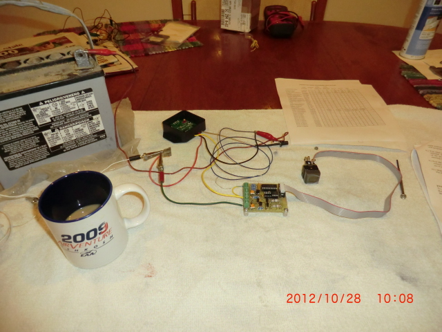
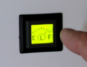
The Aircraft Extras electronic programable display is very cool. It is a tiny display (1”x1”)with the ability to monitor 6 inputs. It be using it to monitor Left and Right fuel level, the main and standby batteries, voltage output of the MAP ( the manifold pressure sensor) which according to Klaus is the best way to monitor power output when used for drag reduction testing and one left over for a spare which I’ll eventually hook up to something to be decided later..? I think after I finish with drag reduction, I’ll connect #5 and #6 inputs to the fuel probes too. This way one can not only get fuel display (my primary use), but I can also use #5,6 to display a RED flashing screen to display LOW FUEL. If that doesn’t get my attention, nothing will! This little display and monitor anything with a voltage output and has LOTS of different display screens to chose from. I may use it to monitor belly board position, oil pressure or ??

wpid-FuelGauge-300-2012-10-27-20-58.jpg wpid-PastedGraphic-2012-10-27-20-582.tiff

A very small system. I only wish it could monitor more inputs (like 16 or 24) instead of just 6. It could be used to monitor anything electrical in the plane. Very cool little device.
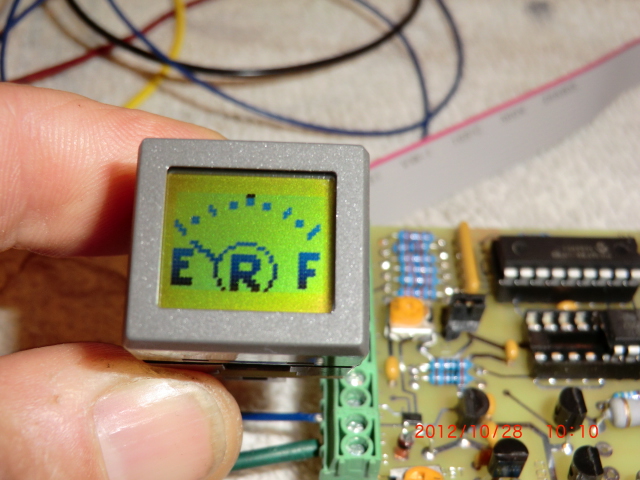
wpid-PastedGraphic3-2012-10-27-20-582.tiff wpid-PastedGraphic2-2012-10-27-20-582.tiff wpid-PastedGraphic1-2012-10-27-20-582.tiff

Naturally, after receiving the AG6, I wanted to test it at home, get comfortable with the programing and operation before installing it in the plane. Ended staying up past midnight last night messing with the display to set it up for my needs. The AG6 VERY easy to configure and program once you get past how the software programing functions.

wpid-CIMG1567-2012-10-27-20-58.jpg

Low and behold I couldn’t get it to work quite like it should. I could tell it was alarming and functioning but there was no backlight color when it was alarmed. A red flashing display is very important to me for the intended use in the plane. The Princeton electronics in the test cell fuel calibrated and worked perfectly but not the readout.

wpid-CIMG1570-2012-10-27-20-58.jpg

This morning it was up early for more testing, more calls to the designer and finally sending him the data settings for evaluation.

Overall it is my goal is to develop a small, complete package of a fuel probe and a readout system for those canard flyers who don’t, won’t, or can’t upgrade their planes to latest Glass Panel type displays. Something that can be easily installed in any canard even if one has very limited panel space (like my plane).

Overall, this is no different from developmental pains of designing the probes. It took almost a year of going back and forth with Princeton Electronics to get the level sensing electronics module working properly. I really like the small foot print of the readout and can’t wait to get it calibrated and working in the plane. It is just a matter of figuring out what is wrong with my setup. After the proper configuration for the fuel level alarms (1/4 tank, 1/8 tank) is determined, the designer will configured and saved the program file so when a canard owner buys one of his readouts for my probes, it will be pre-programed to my specifications so it can be used right out of the box with no fiddling.

After a morning of frustration, it was off to the airport to modify the instrument panel for the readout, wiring and mounting of the electronics which will ultimately occur when the display is working properly. I want to do as much tomorrow as I can as on Tuesday (after install my hydraulic lifters delivery on monday) as it is going to be COLD here (high in the 50’s) which is the result of the Hurricane Sandy which is moving through the area today.

NOTE: After returning the display and getting a new one, I found out that the original display was working perfectly and it was my fault the backlighting (alarms) were not working…. I DIDNT hook up a small jumper wire which powers the light of the display. No backlight power, no colored alarms! Sometimes I am amazed at my ability to frustrate myself.

After reviewing the installation instructions I found my mistake, hooked up the jumper and all the backlight functions of the display worked as designed. The good part of the story is I found the designer was very helpful at trying to solve my self induced problem, and I learned a lot about how to use and program the display.

Watched 3 episodes of a new show on CW called “Arrow”. It is taken from the comics and is about a man who is fighting crime in the city with a bow and Arrow. Sort of like batman with a bow. Actually, it is nicely done.

Sep 07 2011

Belly Beacon

Today’s effort was putting in the new belly beacon light and new dash panel knobs.

The Aero LED belly beacon is actually an interesting story.  At the 2010 Oshkosh airshow while taking to the owner of Aero LED I mentioned it would be nice to have a belly beacon which was also a strobe light.  The beacon would flash red (off/on) like a standard aircraft beacon, and the strobe would be synchronized with the wing strobes.  There is nothing like it on the market.  Apparently after the show Dean (the owner) decided to market the product, he designed it and at the the 2011 Oshkosh show, I purchased it and have now installed it.

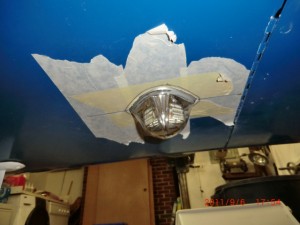
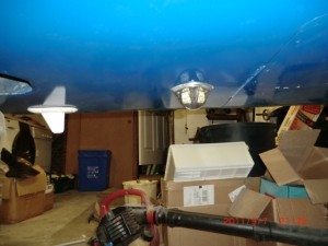
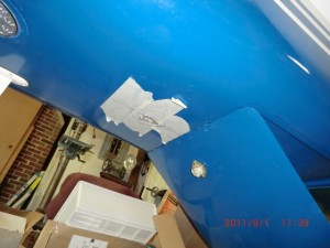
This is the selected position for mounting the light

After checking the strobe on the fuselage I realized it is much too tall for my liking and I didnt like all that metal showing, so I decided to submerge it into the fuselage.

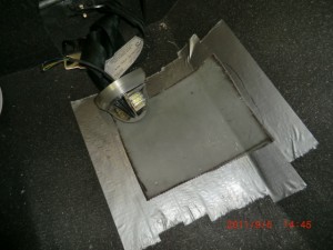
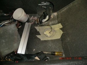
A cover plate was first constructed,

After cutting and sanding the opening, I only left about 1/16″ of the metal showing.

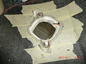
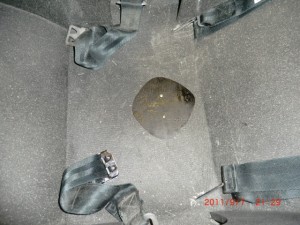
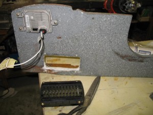
Here is how it looks from the inside.

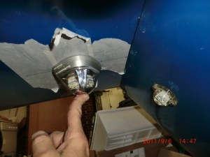
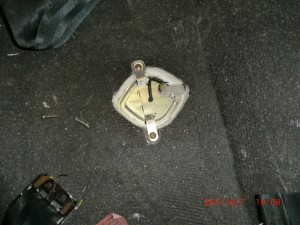
After waxing and taping the light so the micro wouldnt stick, I micro’d the hole with the light in place for an exact fitting into the fuselage.  Next it was installing some hard points to mount the light.

Finally wiring and installation of the light cover.

In this case less is certainly more!  (more better looking)….

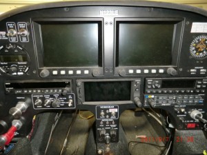
Lastly, wanted to change all the knobs so they would all look the same as the knobs on the Grand Rapids EFIS Panels.  So I ordered the knobs from GRT, made a bushing for some of the shafts due to their non-standard sizes and mounted them.

I think the change gives a more consistent look of the panel….

May 03 2010

Epoxy coating

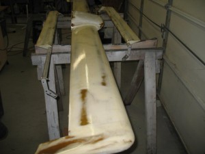
Today was spent on epoxy coating the canard, elevators and micro repairs on the fuselage.  I put 5 coat of west on the uppers surfaces.  It is amazing how well it fills pinholes and scratches.  Tomorrow the bottom surfaces will be coated.    After the epoxy hardens, I’ll be able to sand the surfaces and prime them. 

Fuselage repairs have been coated too.

Between the epoxy applications the mounting of the electrics has begun.  Before the plane is wired, locations most of the equipment  needs to be found.   Clearances checked so you can get the components out if it needs to be serviced (when the plane is fully assembled).    The problem with a LongEZis  how tight everything is.   Without the instrument panel (with the radios installed), it is becoming hard for me to imagine where all the stuff is going to go.   This plane is PACKED with goodies and space is really tight.    One has to imagine electrical interferences (high power lines, transmitter cables, magnetic interferences, ground planes, etc) so everything will work without “cross talk” or noise in the audio system.  What a PITA.

Jul 06 2009

Compartment Heater

I picked up the oil pan today.  It looks great!  Started mounting the fuel injection system on the pan.  Called Airflow, they have the fuel regulator and should complete modifications this week.  When I get it back I can mount all the hardware for the fuel injection, mount the pan and get all the hoses made and installed.  At that time the engine compartment will be completed!   Getting close.

I contacted Grand Rapids and talked to them about the probes issue.  Apparently I as right a resistor that needs to be changed to adjust the capacitance for them to work.  I finished one of them up, and am sending it to GRT where Todd will adjust the circuit and test it to make sure it works.  This is terrific news as now I’ll be able to put in fuel probes for Pat.   This is also great news for the LongEZ community as there has never been a good solution for installation of fuel probes in our planes. 

wpid-IMG_2878-2009-07-6-20-59.jpg

I’ll make another one after I get the modified electronics back at which time I’ll document the procedure for fabricating one.

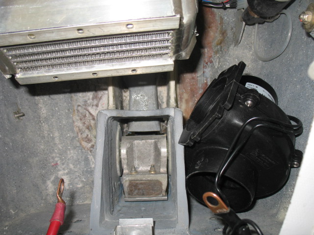
I started on the cabin panels and installation of the heat system.  The blower will go in the nose of the plane along with a oil cooler.

wpid-IMG_2865-2009-07-6-20-59.jpg

I then made a duct system to direct the cool air through the heater.

 wpid-IMG_2869-2009-07-6-20-59.jpg

 wpid-IMG_2872-2009-07-6-20-59.jpg   wpid-IMG_2875-2009-07-6-20-59.jpg  

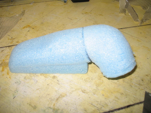
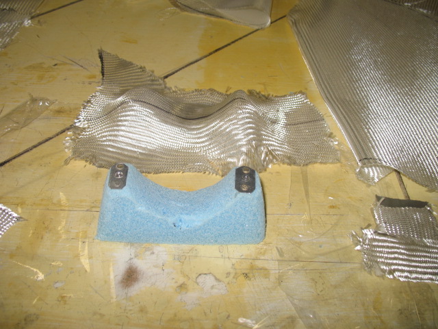
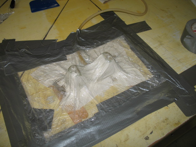
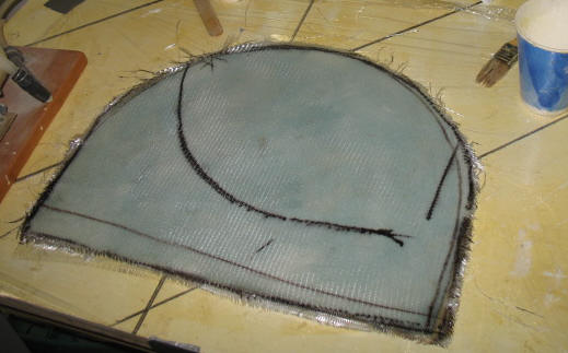
This is the base mount for the fan.  After glassing it, I used the Low-Vac procedure to make sure it conforms to my desired shape.


 wpid-IMG_2876-2009-07-6-20-59.jpg

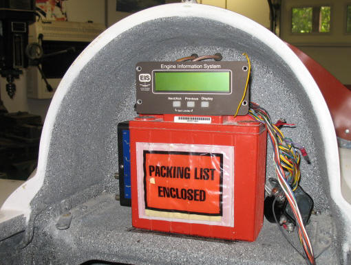
I also glassed the back head rest for the plane which will cover the battery and Engine info system.   Basically, this picture will be the concept for the back headrest area.  You wont be able to see the battery and wiring when the headrest cover is in place.

wpid-IMG_2874-2009-07-6-20-59.jpg

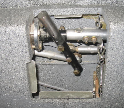
I also installed some tabs so I can mount a cover to hide the stick mechanism.   I have no idea why anyone would want to leave the mechanism exposed.   If you want a light plane, go on a diet, lose a pound and put a cover over the stuff….

 wpid-IMG_2877-2009-07-6-20-59.jpg 

What a long day….  Time to rest.