Still Baffled
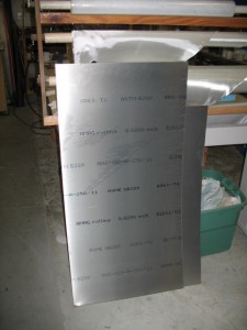
Want to know how to change a nice new 2 ft x4 ft sheet of Aluminum
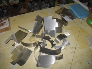
To a pile of beautifully cut and formed scrap pieces?
All you have to do is to cut a pile of scrap pieces of paper and spend a LOTS of of time prototyping an entirely new down draft cooling design…..
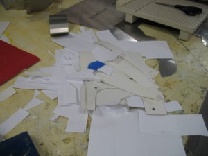
I have spend the last few weeks trying to develop a down draft cooling system totally out of aluminum…. Why you ask. Well if you think of production costs, it is much cheaper to make stuff out of aluminum then fiberglass. Just look at the cost of RV parts. They are really inexpensive when compared to fiberglass, hand molded parts. Machines automate the manufacturing process.
When I started assembling a DD system (change from updraft cooling), I felt the project needed to be modeling in Acad. Faster than manually drawing lines on paper.
Then I got a bug up my b*** and it became a real challenge after I hit on a really simple way to seal the engine. Using seals around the push rod tube. They were very difficult to get right but they work! The tube baffle has grommets for the spark plug wires and fuel injection tube. These seals proved to be the key for the box design. Normally, the only hard part of sealing the engine for DD cooling is the case. As far as the cylinders, they are all the same and there are no variations. So why not just seal what you really need to seal.
Overall, the purpose of this exercise is to to eventually design a kit of precut/bent parts which could be waterjet cut in mass, sold cheap, which allows a builder to assemble a VERY TIGHT down draft box and reduce plane cowl height. Never been done for a canard aircraft. What, we could actually have a something manufactured for our EZ’s which is cheap? Who would have thought…. The kit is applicable to a 320 or a 360, pusher/tracker setup (I think it would be great for an RV). RV’s could get rid of that red silicon seal material.
What I like most is when the builder is trying to balance the cooling on the engine, you only have two cylinders to work (the box only covers two cylinders on each side) with and since the cylinders furthest from the inlet are the coldest, it is very easy to block the box at the half way point to raise the temperatures of the remaining cylinder.
I went though a number of different designs…..
Design #1
Design #2
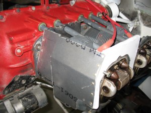
Design #3
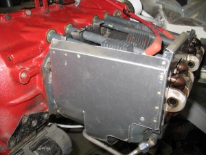
Many different tube seal designs, lots of paper prototype parts
Design #4
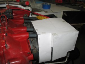
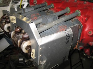
Finally, got it! Here is the final design (the Al still it has the protective plastic on the metal). Late after the cowl is finished, the plastic will be removed.

There is a sliding hatch held on with one screw which allows easy access to the spark plugs.
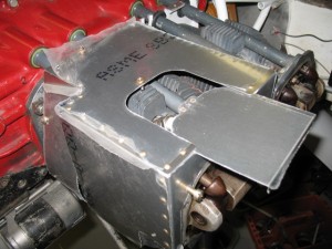
All the parts just seem to majicly lock together almost like a chinese puzzle with a minimum part count. Sometimes I even amaze myself! Now the parts can be mass cut with a waterjet machine which means the kits will be very cheap and easy to reproduce.

If nothing else and they are never manufactured, when I get around to modifying my other planes for DD cooling I’ll be able to make the DD cooling box in a day. I’ll finish assembly of the box tomorrow.
