Oct
21
2009
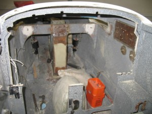
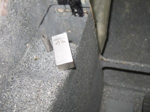
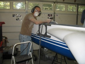
Today was a somewhat short day. I hollowed out the area needed for the rotary latch from eznoselift.com
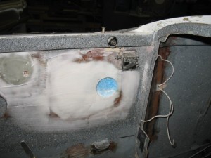
The vent tube was also installed from the NACA duct. Tomorrow, I’ll do the final install of the port/stbd side panels and the eyeball vent
Oct
16
2009
Today Ken Laundry called me to discuss the oil heat system. He was questioning the flow of the oil and the external vernitherm valve. After opening my own website and reviewing the piping layout I realized that I had piped pPod wrong…. Oops! It was piped where the hottest oil would first flow through the cabin then the external cooler, instead of the external oil cooler and THEN the cabin. This would result in much hotter cabin heater temperatures. It would have worked fine as piped but the goal is to keep the cabin heater as constant and as cool a temperature as possible.
After verifying mistake in the shop, I commenced to re-pipe the oil outlet of the engine. Fortunately, it only required some piping which I had on hand and most of my work day. Since it was I who messed up I would never charge my customer for the cost of the rework. The import thing is that the system is properly installed.
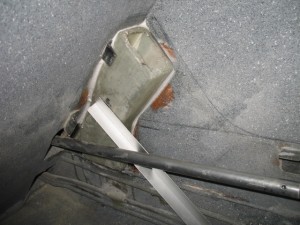
I spent a hour or two glassing the back side of the NACA duct. Not a great day, but it was successful on all accounts…..
Oct
12
2009
Today was spent getting ready for glassing. I installed all the hoses I purchased last week which felt like a real step forward! Had to order some Adel clamps to install the hose system. This is the oil line. It could have been made with a singel hose, but I prefer to minimize the use of hoses and replace as much as possible with hard tubing. It will last the life of the plane and less chance of leakage.
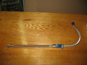
The fuel hose requires a covering of fire stop for safety reasons.
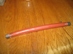
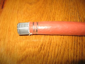
Really like the cheap little tool you can buy which allows you to use safety wire to make hose clamps instead of ….hose clamps. I hate SCAT tubing and think hose clamps are ugly. In this case they were not needed anyway, so why use them.
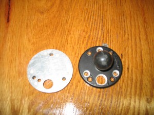
I have to make some support plates for the RAM mounts in the front seat. I dislike wires showing unless absolutely necessary. When you see a plane with lots of wires showing it is an example of poor planning. Something was added after the plane was flying so the wires could not be submerged or hidden. In pPod’s case, all components are known so there shouldn’t be later add-ons. A hole was drilled in the RAM mount to allow the passage of the wires for the GPS. The base will be heavily glassed into the the plan to all it to support any weight component (such as a Garmin 496 or 696 GPS) which can be attached to the mount.
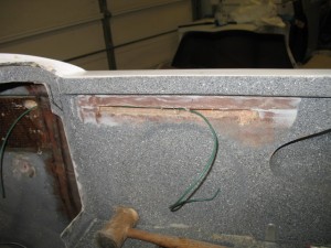
I tried tunneling through the foam to pull the wires though (to hide them), but gave up after a while in frustration so a slot was cut and the foam hollowed out. When done, it will be glassed over for an invisible repair. Isn’t fiberglass great stuff!
Oct
09
2009
I won a free copy of Windows 7 Ultimate for having a Windows 7 Launch Party at guess where….my house!! It is a strange way Microsoft is introducing the new operating system. So next week on the Oct 23, I have invited a bunch of friendsover to see the new operating system and have some burgers and beer. Should be fun! I have already received my party package complete with streamers, napkins, cards, and a bunch of other shit and my free software. Actually, I am so enthusiastic with the software, it wouldn’t have taken much for me to have a party to show off the features anyway.
Because of the party, I decided my computer desk need to be refinished. I was a bit embarrassed with my grungy desk and it needed a new look if I was going to have guests over checking out the new software. The refinishing came out great, but my computer was disassemble and posting wasn’t possible. This will be a quick catch up on this week’s activities.
The instrument panel is now cut out. I hope to start cutting instrument openings next week.
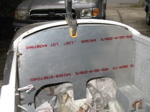
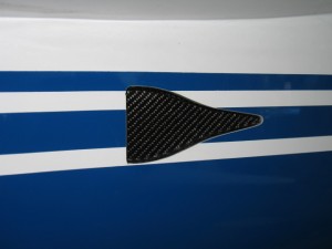
The submerged NACA scoop came out really nice. All work was done from the inside of the plane so no repainting was necessary .
The inside part of the NACA.
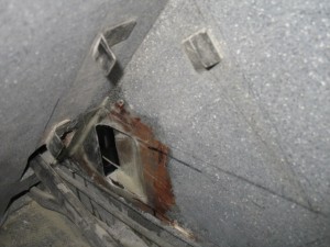
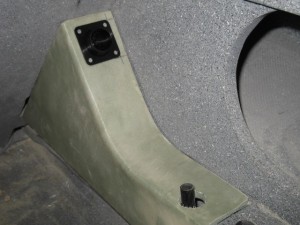
I made a duct from the NACA to the eyeball vent which will be installed on the the arm rest cover. It has a little bit of a weird shape to clear the aileron torque tube. I also will install a pilot controlled door in the the vent duct to allow for pressurization of the cabin when flying in rain or when extra ventilation is needed.
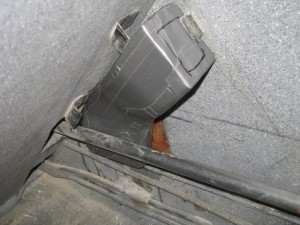
This is how the vent will look in the back seat.
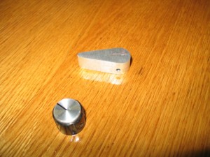
I was going to use a piece of Alum to make a control handle for the overboard oil heat door, but after I made it I found it weighted in at 15 grams.
I then remembered I am using the same style knobs for all interior electrics controls and can also use it for the heat door. The knob only weight 8 gms for a savings of 7 gms over the Alum part and it works just as well. It will give me a more consistent look for the interior. I will recycle the alum part for an exterior canopy latch.
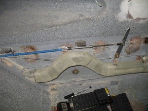
The purge valve dump push/pull system is completed. I have started checking out options for the wiring install.
Oct
01
2009
Today was spent cleaning up the NACA opening and glassing the back side of the flange of the instrument panel. The purpose was to add a more strength to the flange and being solid glass (instead of a sandwich of glass and foam, I can tighten the screws tighter to provide better clamping force for the instrument panel.
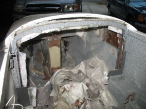
I first removed the foam core from the back side of the old panel. What a messy job!
Then seven layers of glass was added to the flange along the sides of the plane.
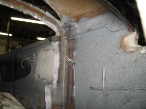
I decided to use West Epoxy (instead of MGS) because of West’s superior adhesion quality.
Tomorrow I am flying down to Tampa to visit Jerry Snider who just completed his Cozy 4. On Saturday Vance will be conducting the first flight. Sort of like giving birth….. Ah, I remember the day well when I first flew Tweety. Quite memorable. Vance and I will conduct an exhaustive inspection of the plane on Friday and after the flight on Saturday it is celebration time!
5.1 hrs worked today.
Sep
30
2009
Today was a busy day. After bonding in the NACA duct, I sent off the ADS-B reciever to NAV Worx for a software upgrade and the addition of a ARINC-429 module. It will all the plane to get traffic information (TCAS) like the Zaon XRS receiver. Cool
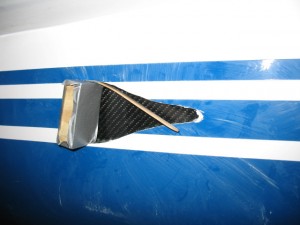
Bonding in the NACA
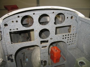
The was also a momentous day. The instrument panel is GONE. Looks kind of weird without it in place. Tomorrow I will strengthen the flange to mount nut plates. I will remove the 25 lb foam from from the old panel and put 6 layers of glass on the back side so there will be good clamping force where it is most critical.
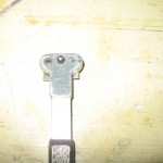
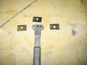
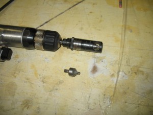
I wanted to show you a useful tool you might not know about. I needed to make 24 nut plates for the panel. This tool is a drill template for the rivet nut. You first drill a hole in the aluminum. Position the too and drill the rivet hole in the guide, flip the tool over (there is a pin on the other side) then drill the second hole. The guides ensure the rivet holes are properly spaced for the rivet nut.
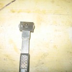
This is a micro adjustable countersink. It is a great tool to use for countersinking the holes for flush rivets. Highly recommended.
7.6 hrs worked.
Sep
29
2009
Today I boxed up the fuel servo and sent it off to Airflow Performance for modification. Basically, they are undoing what was done the first time I sent it to them. This is because of the new sump design and changes in bell crank configurations. I hope they aren’t too pissed at me… probably think I am a bit crazy but paying the bill will make them happy.
Work was started on installing a NACA air duct for cabin ventilation. Pat wants a LOT of air in the back seat. Pat flew in the back of another LongEZ and thought it was hot in the back seat. I thought a two inch NACA would be sufficient, he wants a three inch NACA.
After thinking about it, I now feel the larger size is a good idea because installing such a large air source goes along with my ideas on cabin pressurization which is: Keeping a high cabin pressure keep air leaks and water out. I know simple but true. At our last EAA meeting, I gave a presentation on air leaks and was going to give the same presentation at Rough River, but the weather keep me home. Sometime I’ll blog my philosophy for cabin climate optimization which is a somewhat radical view for our planes. In a very simple way it explains why we have air leaks and how to solve the problem. I use it on my LongEZ with complete success.
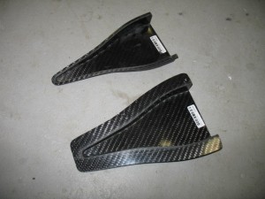
Here is the NACA. I trimmed the edge of the top one (the one I am using) to a constant width of .0180″ to remove most of the flange.
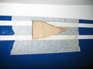
After tracing the NACA on to the side of the plane the skin was removed.
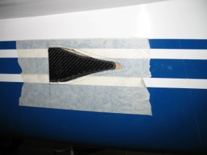
The NACA inserted from the inside of the cabin. I want to try and preserve the paint and striping such that I wont have to repaint the area. A little more foam removal and I should be able to slide it further forward and flox it into place tomorrow.
4.3 hrs worked…
Sep
28
2009
The sump is done! At least the prototype is. It has been sent off to Calif to the fabricator. I cant wait to see the production model!
This weekend was a little of a setback. When started putting the parts in Acad and modeling the sump for the fabricator, I found out it would have been very hard to build. Oops! Back to tweeking the angles, distances, positions until I had a fuller understanding of what was need modeled. After remodeling it again in Acad and all was good.
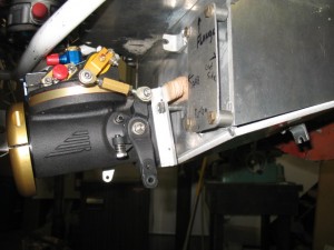
I tried bending mock up tubing to be sure I COULD bend it and adjust for slight differences in tube lengths which is a problem when you are making very short straight runs. I now have to send the fuel servo back to Airflow Performace for a second time to have them reposition the fuel outlet and reverse the mixture valve all of which was done for for first prototype.
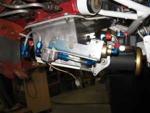
When you look at the first sump, this one is certainly much simpler, easier to build and yes, ..elegant… but lacks the coolness factor of the first one.
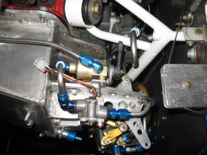
7.3 hrs worked
Sep
23
2009
Yesterday, I continued work on the sump and made 3 fuel probes. One for pPod and two for Toan’s plane. It is surprisingly fast to make them. Now if I could only get Princeton (the electronic’s part) to finish modifying their system so I can use the probes I’ll be set!
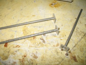
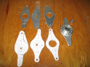
Today, I almost finished the sump. I want to ship it off tomorrow. The last piece of the puzzle was the mixture control arm. I am using a bell crank which is mounted on the shaft of the throttle butterfly. It is mounted to a bearing so each control (throttle and mixture) can move independently even thought they are on the same shaft. Getting the clearances and ensuring it is easy to make for a production enviroment was critical. I designed the arm in Acad then made about six of them adjusting the size, length and angles a little at a time until an optimum combination was found.
The last thing to do is to mount everything, pipe all the fitting to ensure no interferences and ship it off…
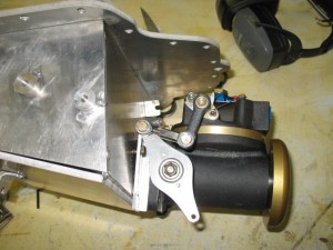
Hrs worked 8.2.
Sep
21
2009
Work continues on the oil sump. I tired all kinds of different positions of the purge valve and flow scan which was very frustrating until I found one which I think is perfect. What I like most about the new sump is that it is very easy to manufacture and you can remove the bracket to do maintenance on the fuel servo. The sump only needs 8 threaded bosses welded on to attach various components. The long welded brackets and bell cranks of the first sump are gone and the piping layout is also simplified. Overall this sump is much simpler, compact and eligant than the first prototype.
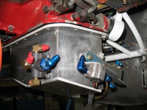
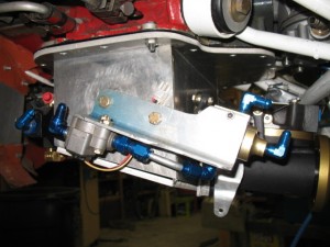
Tomorrow the parts from Aircraft Spruce will arrive and I can make a proper bell crank and mock up the piping. The sump will be sent to the fabricator in Calif on Wednesday for production.
Hrs worked 8.1


