Category: LongEZ Upgrade

Aug 31 2011

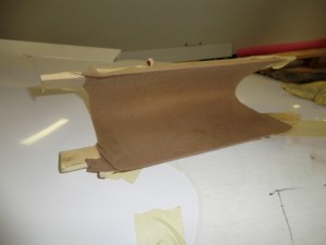
Canard Winglets

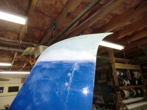
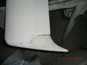
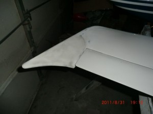
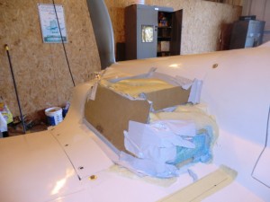
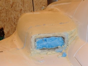
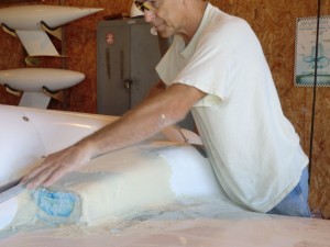
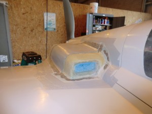
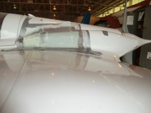
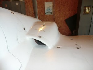
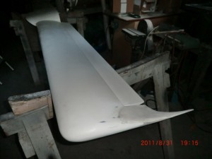
I really liked the look of the top of the winglets so I decided to emulate the same look on the canard.   I don’t think there is any real advantage to the swept back winglets other than looking 10 kts faster on the ground.

This mod only took a few hours.  Over all, I really like the swept back sort of look.

The curvature and shape is exactly the same as the winglets.

I cant wait to fully assemble the plane to see the final look of my efforts.

Next, I’ll so you the cowl mods that I recently completed.   This is a lot more extensive work, but I really like the end result.

Aug 30 2011

Winglet Mods

After a few months of hard work on the plane, I am going to try and get back into my blogging.  A number of people have berated me about updating my site, but to my defense I have been busy and also got a new new computer (an Apple) which has been kicking my ass.  Being an original computer user (before the days of Microsoft and Windows), and a Windows user all my life,  the Apple operating system is a bit of a handful for me…  Anyway,  I am going to try and fill  in the gaps, but for right now, I’ll just cover some of the cool things I have done very briefly.

I now have over 30 hrs flying the bird.  She is a true joy to fly.  BLAZING FREAKING FAST, (top secret at this time), right now I think she is one of the fastest ever built, handles like a dream, terrific avionics (which I can’t figure out how to use) about like my Apple computer but still, this is a plane I really love to keep forever.

As I am finishing up this project, there were a few last minute things I wanted to do prior to flying it to L.A., Calf for painting and upholstery.

James Redmond who likes to race his Berkut pioneered the use of winglet root fairings and sweep back rudder tips in an effort to increase speed.  The speed improvement of the rudder tips (while they looked cool), were hard to measure.  James claims the root fairing gave him a few extra knots, so I had to have them.
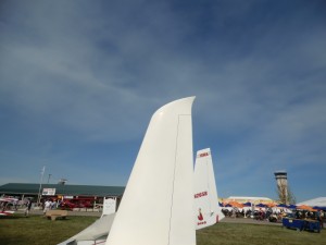
Not to be out done, if a little sweep back on the rudder tips is good, more is better!   I wanted a bit more of an aggressive look.
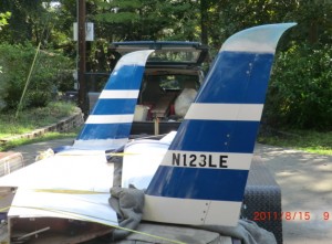
This is a picture of Jim’s winglet root fairing.
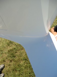
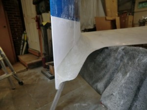
I also did the winglet root fairing too.
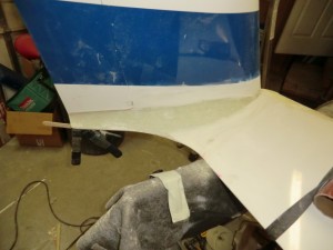
Overall, modification of the wings was a very easy process.  It only took 2 days to accomplish on each wing with one extra day for filling and finishing.

As soon as I figure out how do do web pages, I plan to build a page for each part of the process for others to follow.

Next up is the canard mods..
Jun 10 2011

Cowl mod results

Overall I am very happy with the results of the mod. At 2600 the stbd cylinders are #2 (303f) and #4 (394f). I can easily ballance those two.
The port cylinders are still high. #1 (385f) and #3 (403f). I gained over 200 rpm before the temps went over 400f. I think the inlet duct on the port side is still a problem, so the next step is to clean it up to smooth the air internally.

Jun 07 2011

Cowl mod part 3

Today the cowl was given a new oil door since the original one was glassed over and the forward lip flanges were added to the cowl.

I really the new ducts. The airflow is very direct and open to the cylinders. With blast air directly on #3 (my current hottest cylinder) I should see much better cooling.

Tomorrow, a few nutplates to install, put the baffling back on and the bird should be ready for testing. The cowl mod was started on Saturday and completed on Wed. The work went very quicky.

Jun 05 2011

Cowl mod part 2

Yesterday was extremely busy and super hot out.  Today’s work is much easier  since the only goal is to glass the cowl.

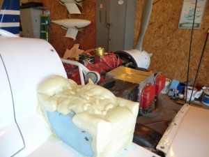
The back section of the cowl was dam-ed and pour foamed.

Carving is the fun part.  You can get as creative as you want before you lock the shape out in fiberglass.

Some duct tape as a release and it is ready to be glassed.

The new shape is beginning to grow on me.  The cowl is much more aerodynamic now.   Let’s let the glass cure before the next step of cowl mods.

Jun 04 2011

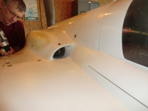
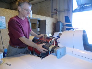
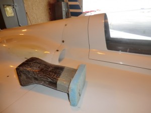
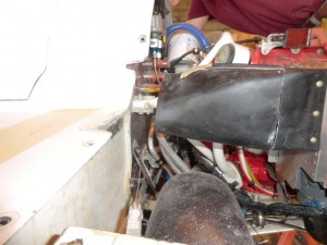
Replacing the inlets part 1

I went flying yesterday and while the cylinder temperatures did come down about 15-20f I am still not able to achieve full power.  The decision was made to cut the inlets off and install a set of inlets I had made about a year ago but never installed. This is the original opening size.  I had removed the shoulder from the cowl and fashioned it into an inlet duct of approximately 7.5 sq inches.

Stbd side.

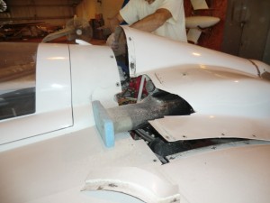
Tony is holding the new duct into postion after removing the old inlet system.

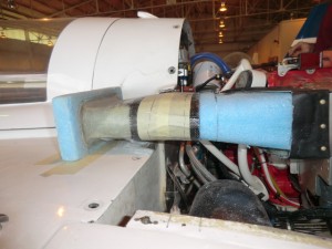
The shape of the new duct is rectangular in opening and MUCH straighter into to the plenum box.  the inlet was fashioned using hot wire cut wing foam. The inlet area of these new ducts is slightly bigger than my plane at about 11.5-12 in sq.

Working the port side was a bit more difficult  as I needed to save part of the duct which


the new nose has been fitted to the duct.

The cowl is cutaway and fitted for the new nose.

the nose section was dam-ed and pour foam was used to fix it in place.

Jun 02 2011

Eductor craziness

The overheating of the engine is driving me crazy.  The plane flies wonderfully well, it is super fast but I cant push it yet because of the cylinder temps being too high.

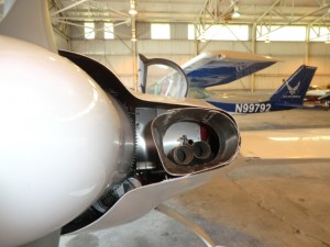
As you saw in my last post, I installed some eductors in my quest to solve the problem.

Nice shape and well built, but when I flew the plane, I only got about 15 f drop in cylinder temps at 2400 rpm but that is not near enough to allow full power operations and the cowl pressure did not significantly change (95 mph at 150 kts same as before installing eductors).     After thinking about it I wondered why my plane which also has eductors cools wonderfully well…. 

After looking at my plane

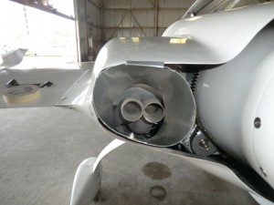
  Port

one can see my eductors are much bigger (both inlet and outlet) and the back of the cowl is compeletelyblocked off.    At 130 kts TAS my cowl has a pressure of 55 mph differental from the cowl to the static port.

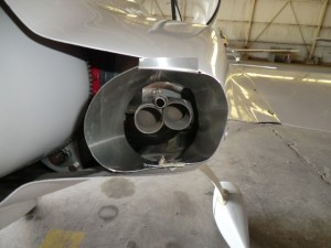
  Starboard

As a last resort, I decided I would try and modify the new plane to mimic my plane.

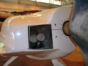
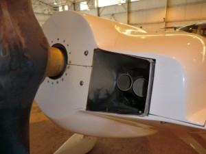
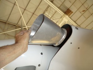
The first thing I did is enlarge the eductors.

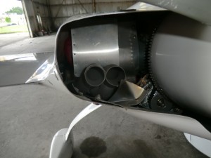
The next thing is to block off the entire outlet to ensure the air only had one way to escape…. through the eductors.

 Port

  Starboard.

After the mods, I went out flying.  The first thing I noted is while taxiing, I had a NEGITIVE pressure in the cowl on the ground, -10 mph and when I increased RPM, the cowl pressure actually decreased!   The eductors really worked and the more exhaust (higher the RPM) the greater the negative pressure.  

After take off the cowl pressure was 45 mph (it was around 80 mph).  The strange thing is, the cylinder temps when up VERY quickly????  what’s up with this?   Maybe it is because the engine was heat soaked waiting to take off, or the fact fact the OAT was at 95 F.  I quickly decided to land to check thing out and on downwind,  the temps had started to decrease.  Tomorrow I’ll fly again when it is a bit cooler and I can do a more extensive testing….  I got to figure out what’s going on!!


May 31 2011

Final eductor tubes are installed.

Today was spent working on the new eductor tubes.

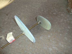
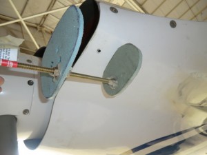
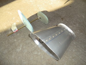
First step is to get an idea of what the eductor is going to look like.   Some foam was used at templates to outline the inlet and outlet shapes as well as the overall length.

The shapes were wrapped with some heavy paper to use as a template to make the aluminum tubes.

The inlet of the tube is flared to smooth the air going into the eductor.

All that is needed is to mount the nut plates on the tube and I’ll be ready to test!  Tomorrow morning I’ll check out the results.


May 30 2011

Temporary Eductors

I have been having MAJOR issues with engine cooling.  I can get up to a max of 2400 rpm before the CHT’s get up to 425f.   Yesterday I decided to go flying before I cut off the front of the inlets and installed larger cowl inlets to let more air in the cylinder plentum boxes.  Sure glad I did as I found out it wasnt the inlet size, but major cooling issue is back pressure in the cowl area.    I thought I would just cut some reverse scoops in the cowl per Jerry Schneider’s SOOMA analysis (Jerry’s famous “Straight Out Of My Ass” method of problem solving).

When I woke up this morning, I realized the only difference between my plane’s cowl (excellent cooling) and the new plane’s cowl is just eductors.  I do not have holes cut in the cowls to let the air out so openings might not be necessary in the new plane, just a set of eductors..  cool!
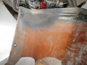
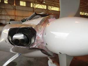
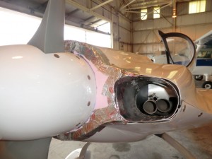
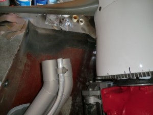
When I went out to the club today and took a close look at the cowls and sure enough,  I notice a LOT of carbon on the cowl just aft of the exhaust pipes.  AaaaHAAAA…  the hot exhaust is basically clogging the outlet of the cowl not letting the cylinder cooling  air out

You can see on the cowl how the exhaust was backing up in the cowl and most likely causing a pressure wave not letting the  cooling air out.

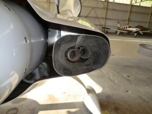
I have two choices, extend the exhaust pipes or build eductors like in my plane, so I fabricated a set quick and dirty set of eductors for testing.


These are the pictures of the cowl and my temporary eductors made out of house flashing, and went flying.

Overall the minimal effort was a very good success as my temps were much better (almost normal) until one of the eductors ripped itself from the plane at 203 kts TAS and was apparently eaten by the prop at which time the temp of #3 (my hottest) cylinder again quickly started climbing up.

I think I am now on the right track and will be building a formal set of eductors tomorrow.

May 02 2011

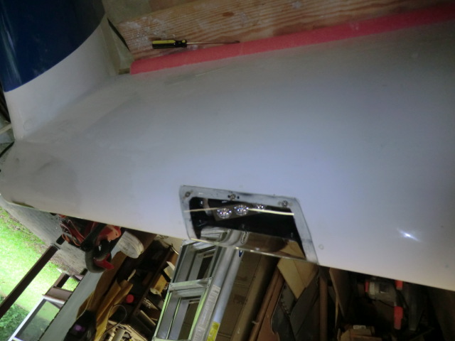
Wing lights part 2

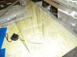
Today I am molding the lens for the wing lights.  After a number of tests I found I could bang them out quite easily.

A couple of notes….

1.  Cover the splash with some fabric.  I found an old tee shirt taped to the splash to prevent wrinkles (which will show up in the lens) after cooling
2.  Heat the oven to about 250F
3.  heat the Plexiglas for about 15 minutes
4. when you removed the Plexiglas from the oven work quickly (as it cools VERY quickly) .  Keep it covered with a warm towel to prevent cooling

Here is a bunch of them made as spares.

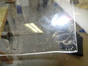
I tried heating the oven up to 350 f and the plexiglass started to bubble.

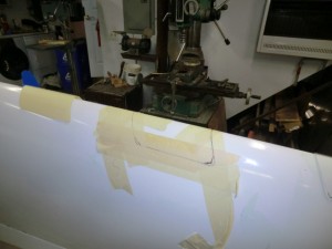
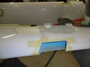
Now that the lens are made I outlined the shape I wanted for the opening and started cutting.

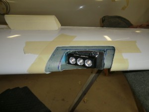
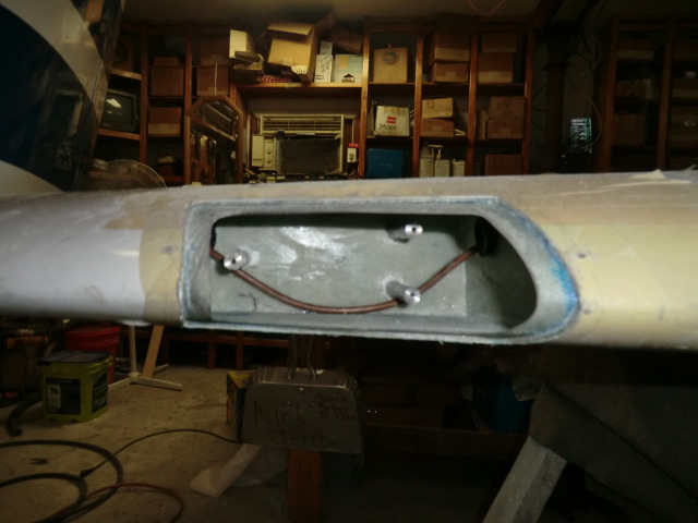
and cut out a cavity in the wing.  You can see the flange on top of the wing will will slid into the opening and floxed in place.

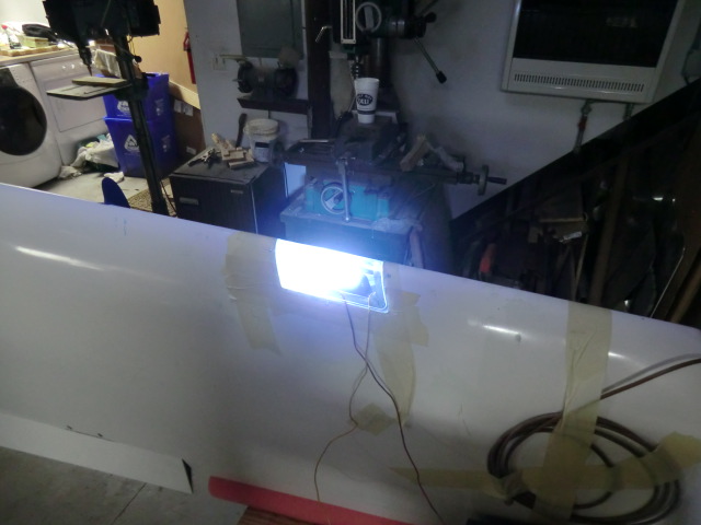
This is how the the lights will look installed.  You can see the lens mounting flange loosely planced in the light opening.

Very cool!

I need to make a webpage on this subject…..  I have lots more details on each step… so many projects and sol little time..  Here is a few more picture for you.


After installation, I wanted to be sure the structure would not be impacted by heat generated by the light.  The light was powered up and I left it on for about an hour to see if the surface of the wing was hot.   The surface was barely warm in static air, so when using the lights in flight the wind will provide a lot of cooling.   So I determined the operation of the lights resulted in no impact to the structure.

Update:  I found the lenses would crack at the screw holes.   I went though a couple of set of lenses, trying different way of attaching them with no joy.   The last time I had my car windshield replaced I noticed they used an adhesive so  I finally decided to just use adhesive to glue them in place (used clear RTV).    Worked great.