Sep 14 2011

Ties downs

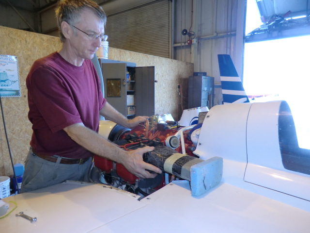
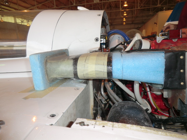
Today was for wrapping things up before I take the plane back to the airport for the final test flight prior to flying to California.

I machined a set of bushing to be floxed into the wings a guss locks for the rudders.  The pins have a little ball bearing in the ends to hold the pin in place when inserted into the tube.  Only thing left to do is to install them into the wing.

I also made some alerion locks for the wing.

This year was a tornado on Wed at the 2011 SNF event.  I was supposed to fly down there on Wed and am really glad that I didnt after seeing all the distruction and damaged planes.

While looking at the damage I happed to come across a big pile of broken “Claw” type tie downs which all failed in exactly the same place.  One thing which was really apparent was that ALL of them failed in exactly the same spot. It is a poor design made of inferior cast aluminum materials.    I have never liked the cork screw type of tie downs either..

I found a much better design called “Storm Force” tiedowns which I really like.  Check out this video

I made my own set for about $10 instead of $100.  All I need is a hammer and bag to complete the set.


Sep 13 2011

Oil Dipstick (updated)

As you may remember I had to move the oil dip stick filler tube outside my inlet plenum to accommodate a smoother flow of air into the engine trying to cool #3 cylinding.  I found a neat idea on the web for makiung a flexible filler tube (cutting the filler tube and using a piece of hose to join the pieces) and a dipstick made from a piece of vinyl coated cable and a custom machined cap.  So I made one.

The problem is you cant see the oil level (especially if it is new clear oil)..  I used some ferrals on the cable (top) to indicate oil level.  Problem is the ferrals got stuck in the tube and again was hard to read.  So I made a second cable (bottom)  with a tube swagged onto the cable.  The idea was to try and mimic the orginal level rod as much as possible to check the oil level.

When I took the oil pan off (to fix some leaks) I found the flexible cable to be really loose and floppy in the oil pan area.  There is no way to get an accurate reading of the oil with this type of system.   Humm…???

The second attempt cable is in the top picture and the updated cable/rod is on the bottom.  Basically I took the cable idea for the flexibility and a rigid tube for readability to make bendable tube/cable level rod ….  The secret to it is a spring near the cap which holds the ridge tubes in compression on the flexible cable.

This tends to keep the level rod perfectly straight off the plane and locks as straight as possible when mounted in the plane.

here you can see the three pieces of tubes bending on the cable.   This allows the level rod to negotiate the bend of the filler tube.

When  released it is perfectly straight.  When checking the cable/rod mounted in the the plane, I found it mimics the original solid dipstick in the oil pan area so now I’ll get accurate reading of the oil level.  Only thing left to do is calibrate it when I get the  oil pan on.

Sep 09 2011

ACES 1050 Probalancer Mod

I purchased a new ACES engine balancer at the 2011 Oshkosh which has some great features I am looking forward to trying out this weekend.  In talking to Gary Hertzler about his experiences using the balancer I found a few short comings with the unit.

First is the mounting brackets.  As you can see there are two sensors (a position sensor and a movement sensor).  Shown are the two brackets.

The right two are the original ones for the sensor, but I decided I wanted them both together for ease of use and to better position them.  Today I constructed the one on the left.

Made of heavy aluminum angle it mounts the sensors on the center line of the crank case.

A second issue with the unit is the power switches.  It is very easy to turn on or reboot the unit as the switches are ultra sensitive.  I took a grommet and cut it in half and RTV glued it to the face of the unit to prevent inadvertent activation of the unit.

Next week I plan to balance the engine on the plane when I get her back to the airport….

Sep 07 2011

Belly Beacon

Today’s effort was putting in the new belly beacon light and new dash panel knobs.

The Aero LED belly beacon is actually an interesting story.  At the 2010 Oshkosh airshow while taking to the owner of Aero LED I mentioned it would be nice to have a belly beacon which was also a strobe light.  The beacon would flash red (off/on) like a standard aircraft beacon, and the strobe would be synchronized with the wing strobes.  There is nothing like it on the market.  Apparently after the show Dean (the owner) decided to market the product, he designed it and at the the 2011 Oshkosh show, I purchased it and have now installed it.

This is the selected position for mounting the light

After checking the strobe on the fuselage I realized it is much too tall for my liking and I didnt like all that metal showing, so I decided to submerge it into the fuselage.

A cover plate was first constructed,

After cutting and sanding the opening, I only left about 1/16″ of the metal showing.

Here is how it looks from the inside.

After waxing and taping the light so the micro wouldnt stick, I micro’d the hole with the light in place for an exact fitting into the fuselage.  Next it was installing some hard points to mount the light.

Finally wiring and installation of the light cover.

In this case less is certainly more!  (more better looking)….

Lastly, wanted to change all the knobs so they would all look the same as the knobs on the Grand Rapids EFIS Panels.  So I ordered the knobs from GRT, made a bushing for some of the shafts due to their non-standard sizes and mounted them.

I think the change gives a more consistent look of the panel….

Aug 31 2011

Canard Winglets

I really liked the look of the top of the winglets so I decided to emulate the same look on the canard.   I don’t think there is any real advantage to the swept back winglets other than looking 10 kts faster on the ground.

This mod only took a few hours.  Over all, I really like the swept back sort of look.

The curvature and shape is exactly the same as the winglets.

I cant wait to fully assemble the plane to see the final look of my efforts.

Next, I’ll so you the cowl mods that I recently completed.   This is a lot more extensive work, but I really like the end result.

Aug 30 2011

Winglet Mods

After a few months of hard work on the plane, I am going to try and get back into my blogging.  A number of people have berated me about updating my site, but to my defense I have been busy and also got a new new computer (an Apple) which has been kicking my ass.  Being an original computer user (before the days of Microsoft and Windows), and a Windows user all my life,  the Apple operating system is a bit of a handful for me…  Anyway,  I am going to try and fill  in the gaps, but for right now, I’ll just cover some of the cool things I have done very briefly.

I now have over 30 hrs flying the bird.  She is a true joy to fly.  BLAZING FREAKING FAST, (top secret at this time), right now I think she is one of the fastest ever built, handles like a dream, terrific avionics (which I can’t figure out how to use) about like my Apple computer but still, this is a plane I really love to keep forever.

As I am finishing up this project, there were a few last minute things I wanted to do prior to flying it to L.A., Calf for painting and upholstery.

James Redmond who likes to race his Berkut pioneered the use of winglet root fairings and sweep back rudder tips in an effort to increase speed.  The speed improvement of the rudder tips (while they looked cool), were hard to measure.  James claims the root fairing gave him a few extra knots, so I had to have them.

Not to be out done, if a little sweep back on the rudder tips is good, more is better!   I wanted a bit more of an aggressive look.

This is a picture of Jim’s winglet root fairing.

I also did the winglet root fairing too.

Overall, modification of the wings was a very easy process.  It only took 2 days to accomplish on each wing with one extra day for filling and finishing.

As soon as I figure out how do do web pages, I plan to build a page for each part of the process for others to follow.

Next up is the canard mods..

Jun 10 2011

Cowl mod results

Overall I am very happy with the results of the mod. At 2600 the stbd cylinders are #2 (303f) and #4 (394f). I can easily ballance those two.
The port cylinders are still high. #1 (385f) and #3 (403f). I gained over 200 rpm before the temps went over 400f. I think the inlet duct on the port side is still a problem, so the next step is to clean it up to smooth the air internally.

Jun 07 2011

Cowl mod part 3

Today the cowl was given a new oil door since the original one was glassed over and the forward lip flanges were added to the cowl.

I really the new ducts. The airflow is very direct and open to the cylinders. With blast air directly on #3 (my current hottest cylinder) I should see much better cooling.

Tomorrow, a few nutplates to install, put the baffling back on and the bird should be ready for testing. The cowl mod was started on Saturday and completed on Wed. The work went very quicky.

Jun 05 2011

Cowl mod part 2

Yesterday was extremely busy and super hot out.  Today’s work is much easier  since the only goal is to glass the cowl.

The back section of the cowl was dam-ed and pour foamed.

Carving is the fun part.  You can get as creative as you want before you lock the shape out in fiberglass.

Some duct tape as a release and it is ready to be glassed.

The new shape is beginning to grow on me.  The cowl is much more aerodynamic now.   Let’s let the glass cure before the next step of cowl mods.

Jun 04 2011

Replacing the inlets part 1

I went flying yesterday and while the cylinder temperatures did come down about 15-20f I am still not able to achieve full power.  The decision was made to cut the inlets off and install a set of inlets I had made about a year ago but never installed. This is the original opening size.  I had removed the shoulder from the cowl and fashioned it into an inlet duct of approximately 7.5 sq inches.

Stbd side.

Tony is holding the new duct into postion after removing the old inlet system.

The shape of the new duct is rectangular in opening and MUCH straighter into to the plenum box.  the inlet was fashioned using hot wire cut wing foam. The inlet area of these new ducts is slightly bigger than my plane at about 11.5-12 in sq.

Working the port side was a bit more difficult  as I needed to save part of the duct which


the new nose has been fitted to the duct.

The cowl is cutaway and fitted for the new nose.

the nose section was dam-ed and pour foam was used to fix it in place.