Jun
02
2011
The overheating of the engine is driving me crazy. The plane flies wonderfully well, it is super fast but I cant push it yet because of the cylinder temps being too high.
As you saw in my last post, I installed some eductors in my quest to solve the problem.

Nice shape and well built, but when I flew the plane, I only got about 15 f drop in cylinder temps at 2400 rpm but that is not near enough to allow full power operations and the cowl pressure did not significantly change (95 mph at 150 kts same as before installing eductors). After thinking about it I wondered why my plane which also has eductors cools wonderfully well….
After looking at my plane
 Port
Port
one can see my eductors are much bigger (both inlet and outlet) and the back of the cowl is compeletelyblocked off. At 130 kts TAS my cowl has a pressure of 55 mph differental from the cowl to the static port.
 Starboard
As a last resort, I decided I would try and modify the new plane to mimic my plane.
The first thing I did is enlarge the eductors.

The next thing is to block off the entire outlet to ensure the air only had one way to escape…. through the eductors.
 Port
Port
 Starboard.
After the mods, I went out flying. The first thing I noted is while taxiing, I had a NEGITIVE pressure in the cowl on the ground, -10 mph and when I increased RPM, the cowl pressure actually decreased! The eductors really worked and the more exhaust (higher the RPM) the greater the negative pressure.
After take off the cowl pressure was 45 mph (it was around 80 mph). The strange thing is, the cylinder temps when up VERY quickly???? what’s up with this? Maybe it is because the engine was heat soaked waiting to take off, or the fact fact the OAT was at 95 F. I quickly decided to land to check thing out and on downwind, the temps had started to decrease. Tomorrow I’ll fly again when it is a bit cooler and I can do a more extensive testing…. I got to figure out what’s going on!!
May
31
2011
Today was spent working on the new eductor tubes.
First step is to get an idea of what the eductor is going to look like. Some foam was used at templates to outline the inlet and outlet shapes as well as the overall length.

The shapes were wrapped with some heavy paper to use as a template to make the aluminum tubes.

The inlet of the tube is flared to smooth the air going into the eductor.


All that is needed is to mount the nut plates on the tube and I’ll be ready to test! Tomorrow morning I’ll check out the results.

May
30
2011
I have been having MAJOR issues with engine cooling. I can get up to a max of 2400 rpm before the CHT’s get up to 425f. Yesterday I decided to go flying before I cut off the front of the inlets and installed larger cowl inlets to let more air in the cylinder plentum boxes. Sure glad I did as I found out it wasnt the inlet size, but major cooling issue is back pressure in the cowl area. I thought I would just cut some reverse scoops in the cowl per Jerry Schneider’s SOOMA analysis (Jerry’s famous “Straight Out Of My Ass” method of problem solving).
When I woke up this morning, I realized the only difference between my plane’s cowl (excellent cooling) and the new plane’s cowl is just eductors. I do not have holes cut in the cowls to let the air out so openings might not be necessary in the new plane, just a set of eductors.. cool!
When I went out to the club today and took a close look at the cowls and sure enough, I notice a LOT of carbon on the cowl just aft of the exhaust pipes. AaaaHAAAA… the hot exhaust is basically clogging the outlet of the cowl not letting the cylinder cooling air out


You can see on the cowl how the exhaust was backing up in the cowl and most likely causing a pressure wave not letting the cooling air out.

I have two choices, extend the exhaust pipes or build eductors like in my plane, so I fabricated a set quick and dirty set of eductors for testing.


These are the pictures of the cowl and my temporary eductors made out of house flashing, and went flying.
Overall the minimal effort was a very good success as my temps were much better (almost normal) until one of the eductors ripped itself from the plane at 203 kts TAS and was apparently eaten by the prop at which time the temp of #3 (my hottest) cylinder again quickly started climbing up.

I think I am now on the right track and will be building a formal set of eductors tomorrow.
May
19
2011
I am playing catch up on the blog once again. The plane is flying now and I am fighting high oil and cylinder temps….
Speed is great. 160 kts at 2380 rpm. So far she has been up to 186 kts IAS flat out for a short time. Still trying to figure out how to interpret all the information I am getting from the GTR EFIS. Now that the plane is at the airport, my evening are a bit more free and I’ll try to get you up to date…..
UPDATE: Today I went flying and at 2500 ft 2900 rpm top speed of 208 kts (240 mph) TAS was obtained. I easily went up to 220 kts (253 mph) TAS on decent. Wow!
May
11
2011
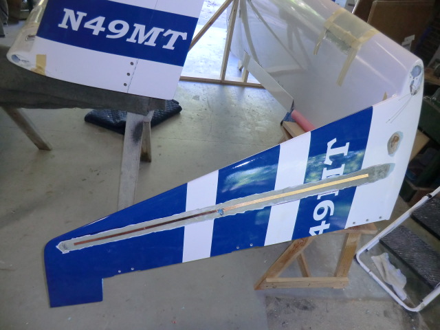
Today I found a number of delimitation on the canard which need to be repaired.
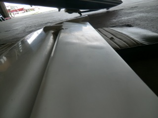
Delam can happen anytime, but I have seen it more often on new wings/canards. Not a big deal and is very easily fixed.
The following the best and overall quickest way I have found to take care of blisters (delams from the foam). This procedure is ESPECIALLY useful for painted or highly curved surfaces because of the absolute minimal damage to the surface.
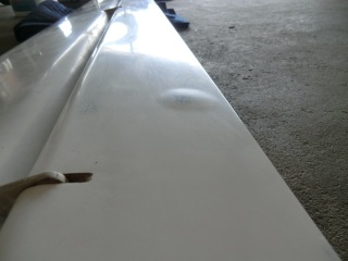
- Take a chunk of foam scrap (I like wing foam), place a piece of sandpaper near the area (sandpaper side up) and sand the foam to make a contoured foam block which matches the contour of the blister area. This is critical for highly curved surfaces such as the canard.
- Put clear packing tape over the area as large as necessary to protect against accidental epoxy drips.
- Identify the exact extents of the delam usually by pressing around the edge (or just looking (optically). I usually mark it with a felt tip on top of the clear tape.
- Drill small holes for epoxy through the clear tape. One at either end for small delams (2 holes) or for large ones, one center and a number around the edge depending on the shape.
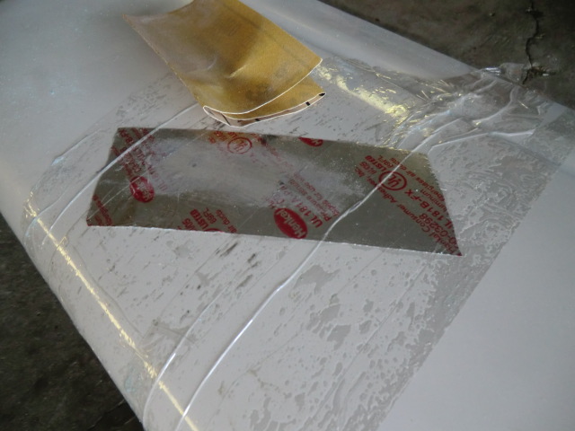
- Cover the clear tape with aluminum tape just over the delam area.
- Locate and reopen the small holes you have just drilled.
- Inject pure epoxy in the center hole for large delams or one end for small delams.
- Make sure the epoxy flows out the vent holes by pressing and squeezing the blister. Squeeze out as much as possible from the vent holes. Excess epoxy will result in a bump on the surface when cured.
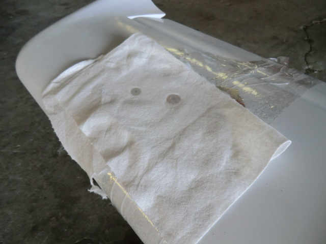
- Put a piece of peel ply then some paper towel on top of the alum tape
- Put some clear plastic on the paper towel
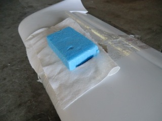
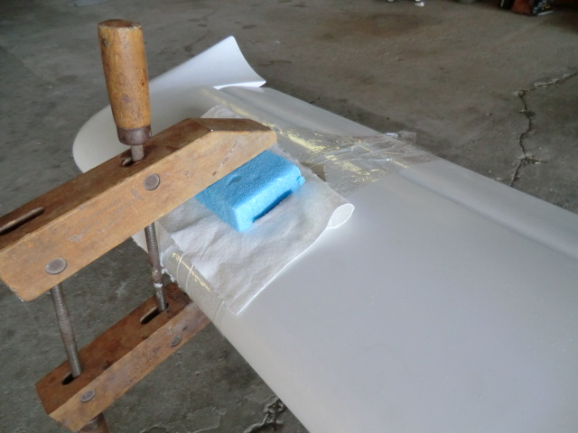
- Place your contoured foam block on top of the plastic and weight it down (the more the better) or if you have room clamp it down.
- Let cure
- Remove weight (clamp)/foam/plastic and yank off the paper towel and peel ply
- The peel ply allows you to really get vertically all the epoxy off.
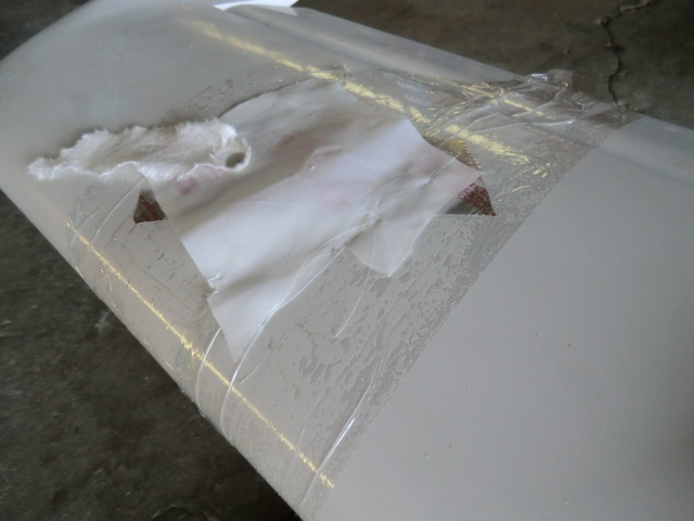
- Using sand paper carefully sand the small epoxy “pipes” that are formed at the hole site. Note:The alum tape is hard to sand though so it is easy to aggressively sand off the excess epoxy at each hole without damage to the surface.
- Take off the alum tape
- Remove the clear tape
Now you will be left with a perfectly matched contoured surface with NO epoxy on the paint, and you’ll only have just a few small clear little tubes of epoxy remaining. If you want you can sand the tubes off with 1200 grit and polish, but using this techique results in almost nothing at all except a tiny clear bump on the surface and I don’t worry about it..
I know this sounds a bit long, but is is just technique and the steps go very quickly. Most importantly, the surface is totally protected and you’ll end up with a properly contoured surface with almost no damage to the surface. It saves time in the long run.
I hope this helps.
May
02
2011
Today I am molding the lens for the wing lights. After a number of tests I found I could bang them out quite easily.
A couple of notes….
1. Cover the splash with some fabric. I found an old tee shirt taped to the splash to prevent wrinkles (which will show up in the lens) after cooling
2. Heat the oven to about 250F
3. heat the Plexiglas for about 15 minutes
4. when you removed the Plexiglas from the oven work quickly (as it cools VERY quickly) . Keep it covered with a warm towel to prevent cooling

Here is a bunch of them made as spares.

I tried heating the oven up to 350 f and the plexiglass started to bubble.

Now that the lens are made I outlined the shape I wanted for the opening and started cutting.

and cut out a cavity in the wing. You can see the flange on top of the wing will will slid into the opening and floxed in place.

This is how the the lights will look installed. You can see the lens mounting flange loosely planced in the light opening.

Very cool!
I need to make a webpage on this subject….. I have lots more details on each step… so many projects and sol little time.. Here is a few more picture for you.

After installation, I wanted to be sure the structure would not be impacted by heat generated by the light. The light was powered up and I left it on for about an hour to see if the surface of the wing was hot. The surface was barely warm in static air, so when using the lights in flight the wind will provide a lot of cooling. So I determined the operation of the lights resulted in no impact to the structure.

Update: I found the lenses would crack at the screw holes. I went though a couple of set of lenses, trying different way of attaching them with no joy. The last time I had my car windshield replaced I noticed they used an adhesive so I finally decided to just use adhesive to glue them in place (used clear RTV). Worked great.

Apr
30
2011
After the splash was made of the leading edge of the wings, a flange needed to be made to support the lens. I used 4 layers of bid.

After wetting out the BID, it was placed in the wing splashes to set up.

Here you can see the splashes (left) the flange parts (right) lights and the 3 way supports for the lights to allow them to be aimed (adjusted).

Apr
29
2011
Today, Tony and I moved the wings from the airport to the house for mods… I am going to put an antenna in the stbd wing and wing lights in to the wings.

The antenna location.

the surface was ground down though the micro, the antenna installed (checked with a SWR meter), one layer of glass to cover it and micro’d.

A splash was made of the wing leading edge in the location of the wing lights. I needed to do this to mold the Plexiglas lens.

Apr
28
2011
After a close inspection of the prop, I found delamination of the carbon exterior near the hub. I have had this happen on my Hertzler prop. I am not sure if it is a result of heat or the compression of the wood at the hub.

To repair, I injected west epoxy into the delamination, heated it and used a vacuum pump to compress the surface to reattach the glass to the wood.

after a few hours of curing, it looked great!

After repairing the prop, I was able to get the engine running. It started immediately! Click on this link to view the video. First Engine Run!
Apr
27
2011
I decided to try a second type of earth bucket. The first type of earth bucket was a pain to make. I felt if I just used gravel (river stone) as a storage medium would make the earth buckets much easier to fabricate, although it would not store as much water.

I tested river stone (small stone) or the larger decorative stone. Much to my surprise the decorative stone held a little more water. A little over 3/4 of a gal. Yah! The river stone can be purchased for about $3.50 per bag and the two bags will make 3 earth buckets.

To make the bucket, a center tube (3″ pvc) is cut about 8″ long. I put tape across the top to prevent the rock from filling the “wick” tube. I then filled the bucket with gravel to about 1″ below the wick. Drill some holes in the side of the bucket at the top of the gravel layer to allow excess water to drain out.
I found it easiest to install the fill tube after filling with gravel . After inserting the fill tube, I covered the gravel with some weed barrier cloth, cut open the center tube to allow the dirt to fill the wick tube and filled the bucket with water. I am not sure if you really need to cover the gravel or if you can just put soil directly on the rock. I am sure the soil would not migrate into the rock area very far. Put in your plant, and fill the storage area with water and you are done.

The plane is looking good! Soon I’ll be flying her.


 Port
Port Starboard
 Port
Port Starboard.


