Category: LongEZ Upgrade

Nov 28 2009

Wiring has begun

This has not been a busy of a week for me.  I was sick the first part of the week and with Thanksgiving thrown in, the work on the plane slowed a bit.  I was able to complete a few items.  I built a O2 bottle support which came out very nice.  The bottle is the same size as a 4″ PVC pipe which I used as a form to lay the glass on. 
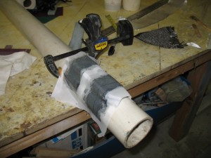
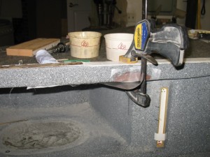
Attaching the support for the closure clasp.
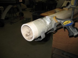
Finished.  Painted flat black.
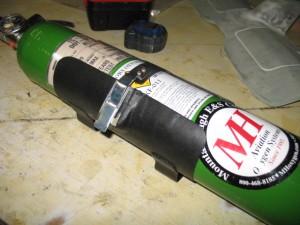
Insturment Panel

I have changed the plan a bit and now want a carbon instrument panel.  Quite a few hours this week was spent finalizing and rechecking the Acad drawing so it can be cut out on a CNC machine in LA.  I should have a test panel in a week or so.  After I finish installing the supports and lettering it,  the panel will go back LA for clear coating and polishing. 

WIRING

I also started working on the wiring system.  I have been avoiding the wiring just becauseI know how much work it is truely going to be.  Many, MANY hours sitting at the computer drawing and documenting the wiring harness.  After installation, there will be many hours of correction the drawing for final printing.   I laid out all the major electrical components on my spare bed and looking at all the wiring ahead is daunting!
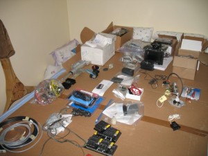
IMG_3842   

The wiring diagrams are absolutely CRITICAL to long term maintenance of the plane and they need to be as complete and clear as possible.   After flying these planes for years, I find most of the maintenanceissues in the future will mainly be wiring problem.  Fixing a screw, bushing or engine component is quick and easy.  Finding out why a light or radio stops working is really tough and almost impossible without a well documented wiring schematic.    The type of connectors, switches, plugs, type of crimper used, wire, etc should be of the highest quality possible, because it will bite you in the butt if  you dont pay really close attending to this critical aspect of the plane.    Of all the work I am doing on the plane, I approach this area with the greatest concern and closest attention to detail possible.    This is why it takes so much time and effort.  I spent 3 hrs yesterday working on just 4 pages of wiring and I am still not done.    I will probably have 30 or 40 drawings.   

Some people approach the electrical draw from the aspect that you should put everything in an area on one page.  An example is the power system should show all components and where they all go (charging, starting, lights, lines to the radios, etc).  This is great for wiring the plane, but doesn’t help as much when you are trouble shooting a sub area of the larger system.  Lets say you are only working on the alternator part of this system.  

I like drawing the areas out in sub systems.   The alternator system is drawn separately from the starting system or the ignition system.   In the future when you are trouble shooting  problems with the charging system, it is MUCH easier to look at just the system of interest and visually see what is going on.  You dont have to separate it from a larger drawing with lots of other stuff on it.  It makes wiring the plane more of a pain but is much easier to trace wires.   

Anyone can wire a plane… it is not rocket science and is fairly easy to do.  Run a wire from A to B and you are done. Easy.  I have seen so may planes (certified and experimental) where if you ask the owner for a wiring diagram, you’ll get a blank stare.    I have seen very few few wiring diagrams and they were by obsessive compulsive engineer types who really knew the value of having one.   Most builders just wing it.    I had to rewire my plane because of a crappy wiring job and no documentation and did a fair job drawing out the wiring on Tweety.  On this plane, it will be the mother of documentation because I plan to reuse most of it on my cozy 4 (Bubba) so it is worth the extra effort.    Beside, I want to do it right for myself .

Wire Zip Loops Ties

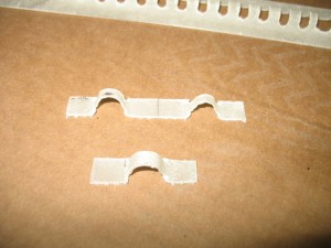
One thing which has always bothered me was how do you attach the wire bundles to the plane.  In my plane I used click bonds with Adel clamps which are heavy and awkward to use.  I wanted something easier to install and more versatile.    So I made up some attachment point I call bow-ties.

First I layed some glass over some small diameter rods.
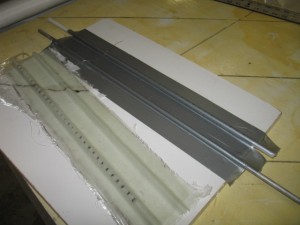
After slotting the glass layup (I used a radial arm saw), you can cut them up into individual loops or as strip and flox them to the surface of the fuselage.  A zip tie to hold the wire bundle to the bow tie and you are done.  I weighed a single zip loop and it works out to .5 grams each.    What I like about it is if you wish to have a number of separate wire bundles (my favorite choice) you can cut a strip of zip loop ties and flox them down as a group.  Then the wire bundles are equally spaced out along the wire run.
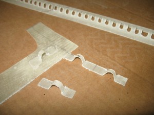
I think may make another strip of ties which will improve my original design.    The first set used a rod as the form and was a very easy way to make a strip of bow ties, but the top of the ties is rounded and a bit taller than I want.  I plan to make a gig which will be squared on the top (3/16″) about 1/4″ high and use 2 layers of carbon.  It will hold the zip ties better and I have plenty of scrap materials around to try it out.
Nov 16 2009

Arm rests

Work started back on the plane.   I finished the cover for the belly board motor.    It came out nice.  Today it was glassed to the foot rest.

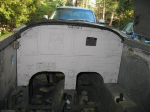
The instument cover actually came out better than I expected.  The carbon graphite is incredibly stiff and it made a really nice cover.  I like the rounded look of the carbon weave. 

The cover is going to be clear coated which will make the carbon really stand out.  It will end up looking great!

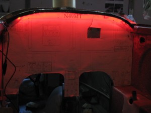
I tried lighting it with the LED strip light which fits under the lip of the panel.   The lighting is nice and even.

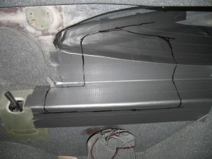
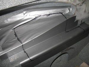
This is the plan for the arm rest.  Typically I like to rest my arms in the strake opening.  The sharp edge of the stake is very uncomfortable on the elbow, and it occurred to me to pad not only the flat surface but some of the strake area too.    After glassing the panel it will be covered and RTV to the plane.   I use RTV in my plane to hold my arm rests which has worked out very well over the years. 

Stbd side.

Port side


Nov 11 2009

Instrument panel cover

Today was spent working on interior panels again….  Pat wants a cover for the belly board electric motor.  I’ll show pictures of that tomorrow.  The eye brow cover for the instrument panel was also worked on.  It turns out it is actually quite complex to make due to the curvature of the canopy and the desire for a lip to hide the LED lighting.   

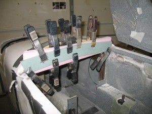
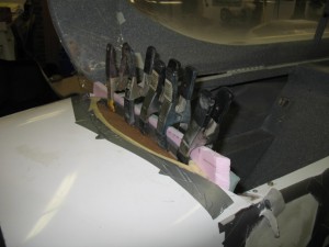
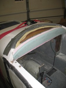
First, foam was glued to the face of the instrument panel.  Two thicknesses of foam was used to get the necessary thickness and the green foam allows the radius to be easily judged for consistency.


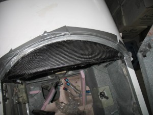
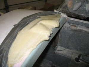
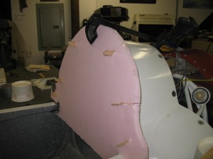
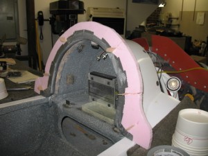
Some cardboard was placed forward of the panel and expanding foam was poured into this area and the canopy was closed.  After the foam expands and sets a perfect image of the inside of the canopy will be formed.  it will be easy to then sand the foam to a pleasing shape and glass with carbon graphite.

After using pour foam and closing the canopy, I had an exact impression of the canopy which could be sanded to make the support form of the instrument cover.

IMG_3768

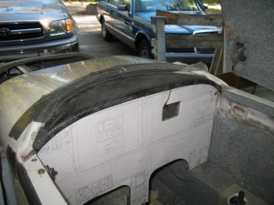
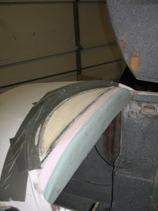
After sanding to shape.

Taped, waxed and ready for glassing.

Nov 09 2009

Extra Storage Area

I was out of town this weekend.  Flew up to PA to visit Mom and fix her TIVO.  The trip was GREAT and my average speed was about 190 mph.  Cant beat that!  The OAT got down to 27 F at 8000 ft and Tweety’s oil heat system worked great!   The toes got just a little cold, but I wasnt even wearing a jacket, just a light shirt.   The main problem is getting enough air to the nose of the plane from the heat core installed under the back seat.  I will probably rip out the SCAT tubing I used (hate the stuff) and make some fiberglass tubes to reduce the head loss in the system like in pPod. 

With pPods nose installed oil cooler and tight sealing of the nose area to reduce drafts, the plane should easily be good down to 10 F or less.  I have never flown below 15 F so we should be good for just about any flying.  Since the plane will be delivered this winter, I’ll have a chance to really test it out.
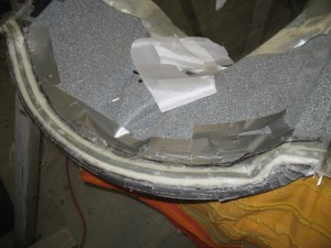
Today was spent mostly preparing for glassing.  I didn’t like the match up of lines on the STBD panel from the old to the new, so I added some glass to the existing installed arm rest.

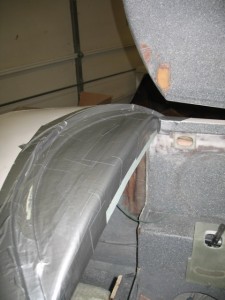
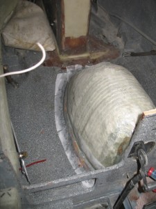
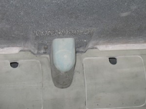
Also glassed was the insulated cover cover for the wheel well.  Insulating the wheel well is very important to keep the heat in during the winter.  You can actually feel the heat being sucked out of you when you are straddling the WW on a very cold flight.  The WW is only 3 layers of glass so it does almost nothing to keep the heat where it belongs… in the plane.

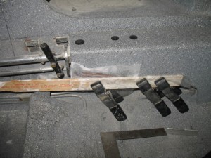
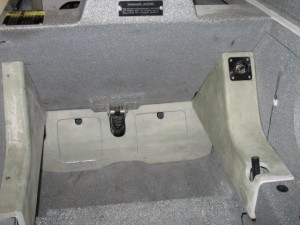
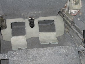
The openings for the rear foot rest were cut and springs installed to let them ‘snap’ shut.  I tried sitting in the plane the the foot support is very good.   I really like the extra storage and may add them to Tweety.

There is actually quite a lot of storage space in them.  I plan to put the ELT in the smaller side.  I want a cover for the actuator so it cant be seen. 

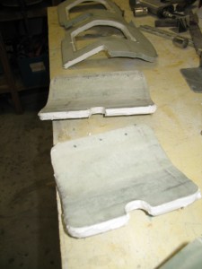
All edges of the doors were filled with micro.  I think is a very easy step and makes the panels look much better.  It also keeps the foam on the panels from ripping off the glass over the years of abuse and allows for a slight rounding of the edges to soften them a bit.   A very important step in my book.

Nov 02 2009

Drip Rails part 3

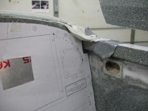
Today was spent entirely spent working on the drip rails.  After sanding, the back one came out beautifully.  The front one has issues.    As it was being sanded and shaped, I wanted to see  if the instrument panel would still properly fit.

SHIT!  The funky shape of the canopy caused the seal area to dip way down which now interferes with the installation of the instrument panel.  I would have to trim and cut off the corners of the instrument panel which is totally unacceptable.   Doing so would work but it would ruin the look of the panel.   I had to step back, re-evaluate the whole thing and come up with a different game plan.  The drip rail needs to be installed no further than the pilot side of F-22 to achieve the right look.

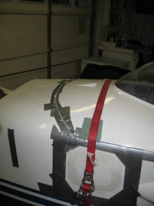
A second seal was placed in micro, and the canopy closed.  Tomorrow, I’ll see how it looks and how hard it is to dig the seal out of the micro.   The thing I really like about fiber-glassing, is I could always cut everything out and start over again if necessary.   I hope that option is not necessary.   The strap around the plane holds the canopy tightly closed while the micro is curing.

Oct 29 2009

Drip Rails part 2

Today was a fun day.  It was exciting to see how the molding that was done on the drip rail turned out.  These are some pictures of the passenger rail.  After the foam was removed it was time to get into the plane and sand/trim.
The rough shape after glassing

Trimmed and fitted to the canopy cover.

The fit from the inside.

It came out perfect. 

So easy a cave man can do it!

I hated be cramped up into the plane sanding and trimming! 

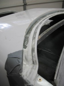
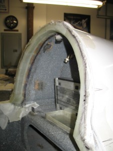
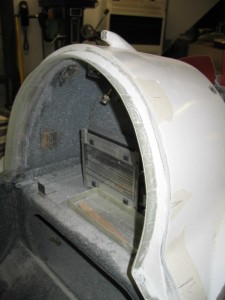
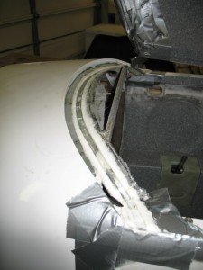
This picture is of the front drip rail.  After glassing a trough onto the canopy a few days ago, the canopy was closed and a rough glassing of the rail was done to transfer support to the fuselage.  The glassing was a bit hard to do (upside down, little space).

When the canopy was opened, the channel for the seal is perfectly fitted and transferred to the plane.  Two more layers of glass will be used to ensure good attachment to the fuselage and finally, micro will be used to dress it out with a nicer finished product.    Overall, these seals will really reduce air leaks when flying and rain when parked.  Well worth three days efforts.

IMG_3737

Worked 6.3 hrs.

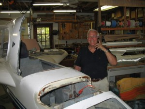
Bob stopped by to inspect the progress on the project.    Had to kick him out after a while because I was on the clock and had some glassing to do before I could quit for the night….    I sure enjoy his visits and support…

IMG_3732

Oct 28 2009

Drip rail fun

It looked strange to see the canopy on the plane as I am working on the drip rails.  Almost looks like a real airplane again!

The front channeldrip rail received the first glassing step.  Tomorrow it will be bonded into the fuselage.

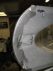
The aft drip rail is a REAL challenge.  When the Longez was first designed, no drip rail was included in the planes.  It was one of the improvements that evolved over time.  IF the plane  was under construction, the fore and aft drip rails would be very easy to install.   It is a real PITA to install one on a completed plane.   This is the second one I have installed and it is getting faster.  First a foam template of both the back and front of the opening needed to be constructed.  The foam panel was made with locator sticks protruding so I could pull the foam off the fuselage and move it to the canopy  to scribe a line so I could get an idea of where the canopy sat in relation to the fuselage.  They were built separately so there was quite and offset between the two parts.

Once the opening was cut out and covered with release tape it was glued to the fuselage so glass could be layed up on it.

Everything is now bonded to the fuselage of the plane.  The hard part is tomorrow when I have to get into the plane, close the canopy and sand the rail down until I get the proper clearance with the canopy closed. 

5.4 hrs worked.

Oct 27 2009

Front Seat Vent

Work was stared on the drip rails.  Normal when someone builds these planes these rails are constructed early in the process.  The also allows for the installation of a weather seal which prevents rain from coming in the plane when parked or when flying.   I personally think they are critical as I have had rain puddled in the back seat, wet cushions, radio issues all from water coming in the plane before they were installed in my plane.    Unfortunately pPod does not have them  and fortunately, I have put them in my plane.

This first pictures show the installation of a 1/8″ thick foam channel which will allow the molding of a small channel for the weather seal.  This rail will require two lay ups.  The first is to mold the channel, the second is when the canopy is reinstalled and it is glassed to the forward part of the plane.

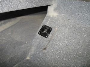
Work was completed on the installation of a front seat vent which is supplied by the 3″ NACA  inlet. 

A butter fly valve was also installed to increase airflow into the cabin.  It is actuated by a lever which goes through to the front seat for the pilot to open. 

Oct 26 2009

Panels part 2

When I opened my paper today, it was a surprised to see my the “Letter to the Editor” which was sent in about the flying saucer balloon stunt was published in the paper.    It also occurred to me if one builds a lighter than air craft,  the designer HAS to know the lift capacity, structural design, loading, etc, so the dad was pulling a scam from the beginning.  He knew the craft could never support the payload of his son.    No matter what his says, he is guilty!

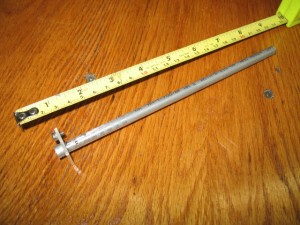
Yesterday, I put a note on my canard group site about some fuel probes I made trying to judge interest from the community.  I have been trying to prompt Princeton into finishing the mods to the electronics module so I can get a set installed in pPod.   I figured if I got a huge number of builder/owners interested in using their system, Princeton might be more responsive to my requests and willing to work with me.    In less than 24 hrs I had over 40 emails wanting to buy some.   When I talked to Princeton this morning he really seemed to perk up a bit with the news!   I am sure the total will increase as soon as I post actual procedures for installation and prices since it really IS the only game in town…  Here is a picture of a production unit I made.   So easy to make a caveman can do it!

I am working hard at trying to compete all the panels in the plane.  I want to paint the interior next week.  Then I can start on the the fun part….wiring! 

This picture is the alternate air door which will be pilot controlled.  You can also see the pull strings  I installed in the foam core for the hidden wires for the iPod and cabin lighting.

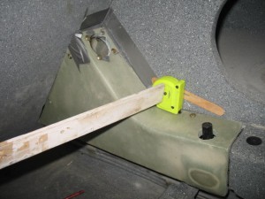
The passenger LED light will be place where the clamp is holding the mount in place.  A soda straw was glassed in to the top of the strake to allow for a wire run to hide the wires.

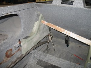
The original STBD side panel also had to be extended down an inch or so to allow the front and rear panels to properly match up.

Tony and his dad (visiting from England) stopped by to get some lessons on molding parts.    Hard to believe his dad is 85.    It is amazing what living in a country with no sun (it rains constantly) will do for the health of ones skin.  He doesn’t look a day over 65!  His wife  (in her 80’s too) has no wrinkles and very healthy skin!

Oct 22 2009

Panels

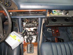
This morning was spent putting a new (old) stereo in Sherman.  I had replace the original in the car for a new one which failed after two years.  I had saved the old one so it went back into the car.  This time I fabricated a 12 pin connector for the car wiring harness.  It will make it really easy replace this radio for a new HD radio with iPod input and Blue Tooth capability easier to do.  Eventually, I want to move up to more modern electronics.


Panels, panels, panels.   Today was a fund day of installing a bunch of panels in the plane.    My goal is to make this plane look close to a car!  I think new cars are a work of art.  Take a good look at a Volkswagen.  Their interiors are beautifully functional, efficient and crisp!    I love the refined, elegant and  luxurious nature of a Lexus.   

When you look at most canards they are wonderfully simple, very light weight, easy to build but unfortunately very basic.  Whenever I get into a nice car, I think why does my costly and major cool looking air plane look so utilitarian and well clunky on the inside.  Uncomfortable, cold, the rain drips comes in, hot, drafty.  Alas, the secret is out.  Tweety has a great looking body, but sort of plane a Jane on the inside (were it counts).    
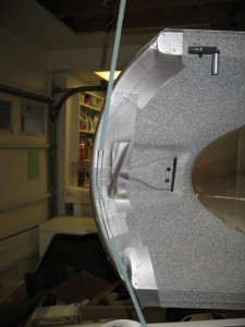
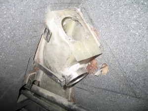
Mygoal with pPod is to use wasted space and to transform her into something closer to the look and feel of a  ….well… and old 1981 Mercedes SD300 Turbo.  What a remarkable idea!   If it is good enough for Sherman, then it is should be good enough for pPod.   To do so I need cover panels….lots of them.

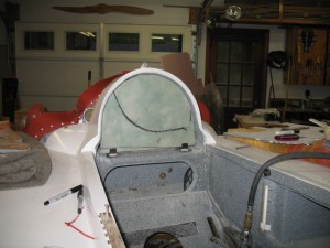
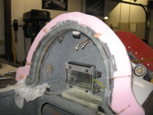
This is the back panel for the rear head rest and cover for the aft (main) battery.


This is the Starboard panel.  At the top will be the eyeball vent followed by the electronics input panel.  I will make a cover for the rear stick so when carrying baggage in the back seat there will be no possibility of interferingwith the flight control system.   Add a nice arm rest panel for a bit of elegance!


This is the Port panel.   A 12v dc outlet and a pocket (accessible from the front seat) will be installed for maps or possibly a new ebook reader.   Pat talked me into making a foot panel and cover for the electric actuator for the belly board.  The foot panels will also have some built in storage.


For those who dont know An eBook reader is you should check them out at Wikipedia.    Even a basic one could easily contain all the approach plates for the entire USA and Canada and plenty of extra room for other reading material.   One wouldnt have to carry so many books and weight for a LONG cross county trip (such as Charleston to Los Angles)  and ereaders are much easier to use.    You can get the approach files at NACOmatic.com .   What a great resource and are FREE and current!

 The only reason I dont buy an eBook reader right now is that in the next 3 months a whole slew of new eReaders are going to being released.  EBooksare the “new” must have technology.   Hell with the Apple iPhone, iTouch you NEED an eBook reader.      Amazon,  Barnes & Noble, Sony,  Freescale, PaperLogic and a host of others are all getting on the etrain and bringing out new and innovative ereaders.   The choices right now are slim and most lack even basic Internet capabilities.   The cost range will be about $150-$400.  A few standouts (Paper Logic) will be about $550 or so due to ‘advanced’ features.  

I am looking for something that will be close in size to a standard approach plate, has WiFi and can interact with the web (so I can do flight planing).  Has to have an SD card slot and support standard .pdf files.    By January 2010, all the first generation choices (black and white) will have been released to market place and a decision can be made.    I’ll have a new toy and the bird will lose a few pounds. 

Here are nine new ereader which will be coming out shortely.

I predict in a few years, ebook readers will morf into a ebook ereader netbook with full Internet capabilities using a color touch screen.  The main difference between an ebook and a computer will be the inability to load programs to create content independent of the web.   The ebook will be able to open and read any format document (with appropriate plug-ins), annotate documents (pdf markup touch screen), display static color pictures (since the electronic ink does not easily change states) and finally get on line (WiFi) and interact with on line programs.  This will reduce the processing power needed on netbook ereader since all the processing and storage will be done on the web (Cloud Computing).     Technology is changing once again to something new and exciting!