Category: LongEZ Upgrade

Jan 09 2016

Oil heat continued

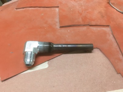
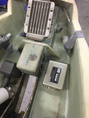
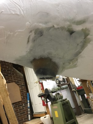
For this version of oil heat, I needed a stand tube for the oil sump.

Tubing was welded to a fitting
wpid-IMG_3939-2016-01-9-21-41.jpg

I was cut 3.5” which hopefully only allow oil to be removed from the sump at a level great than 4.5 quarts. If the sump gets below the level the tube will be come uncovered and protect the engine. This is needed in case of a hose break (unlikely).

wpid-IMG_3941-2016-01-9-21-41.jpg

I needed to move my oil sump drain to a new location since then hole is now being used by the stand tube.

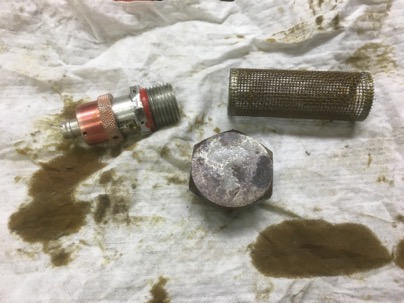
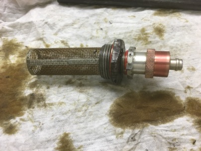
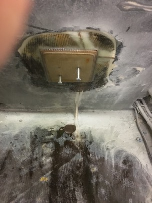
The oil suction filter cap was removed and drilled and tapped for the quick drain plug.

wpid-IMG_3942-2016-01-9-21-41.jpg

wpid-IMG_3944-2016-01-9-21-41.jpg

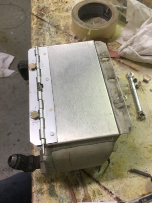
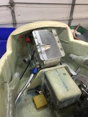
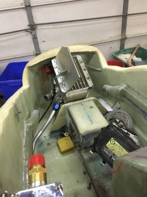
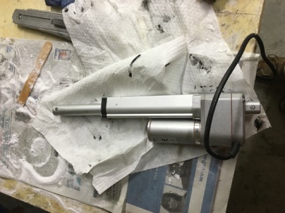
I wanted to control the air from the preheater so a door was fashioned,

wpid-IMG_3950-2016-01-9-21-41.jpg

and a control cable was installed to allow opening/closing the door in flight.

wpid-IMG_3958-2016-01-9-21-41.jpg

wpid-IMG_3959-2016-01-9-21-41.jpg

Jan 04 2016

Ducts are done

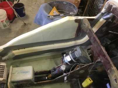
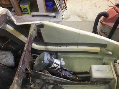
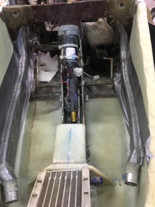
After the foam and tape was removed, the ducts were weighted and installed. Overall, they were very easy to make and will last the life of the plane. I would probably use the idea again for wire chases or more duct tubes.

wpid-IMG_3905-2016-01-4-21-33.jpg

wpid-IMG_3904-2016-01-4-21-33.jpg

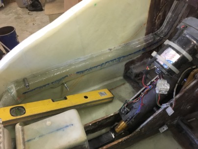
The oil pump mounting location was selected and click bonds attached.

wpid-IMG_3906-2016-01-4-21-33.jpg

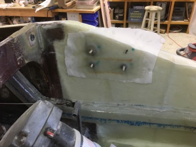
The mount for the electric belly board was installed.

wpid-IMG_3907-2016-01-4-21-33.jpg

Jan 03 2016

Time worked week #8

Week
                Week hours                Total hrs                Weekly average
1
2
3
4
5
6                24.6                                221                        37.0
7                13.1                                235.0                33.6
8                21.9                                256.9                32.1

Jan 02 2016

Air ducts

Ran into a BIG snag… my SCAT tubing (1.5”) is too big to go under my electric trim or elevator servo push rods. Shit!! I consider giving up on my idea of feeding the dash from my nose vent and just install NACA ducts on the side, but then came up with a better design. Custom made air ducts.

Actually they were very easy to make and 1/4 the weight of the scat tubing.

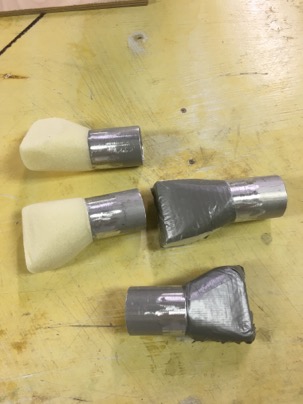
First transition ducts were made to covert the scat to rectangular. I calculated, a 3/4”x2” duct would have the same internal volume as my 1.5” round scat. The 3/4” height would fit nicely behind the push rods.

wpid-IMG_3890-2016-01-2-21-07.jpg

The transitions were floxed to the sides.

wpid-IMG_3891-2016-01-2-21-07.jpg

Duct tape was placed on the sides to protect the existing glass, and 2” urethane foam block was into 3/4” strips and 5 min glued to the sides.

wpid-IMG_3894-2016-01-2-21-07.jpg

wpid-IMG_3895-2016-01-2-21-07.jpg

The foam was covered with duct tape and glassed. Cleco/alignment holes prior to removal to ensure will be precisely lined up when I clean and reinstall the duct.

wpid-IMG_3901-2016-01-2-21-07.jpg

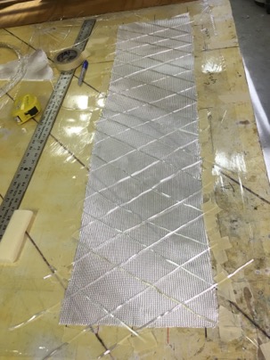
I tried using S glass roving on 1 BID for the glass for these ducts. The S glass did make them stronger but was a PITA to do. Next time I make a duct I think I’ll try 2 UNI at 45 dig angles. I think it would be as light and possibly stronger than what I made this time.

wpid-IMG_38981-2016-01-2-21-07.jpg

Dec 27 2015

Week Report #7

Week
                Week hours                Total hrs                Weekly average
1
2
3
4
5
6                24.6                                221                        37.0
7                13.1                                235.0                33.6
8

Dec 22 2015

Air sperator completed.

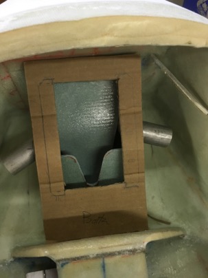
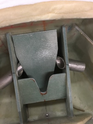
The design of the water/air operator was completed. First constructed out of cardboard, then luan plywood, then foam/glass

wpid-IMG_3836-2015-12-22-20-56.jpg

The funny shaped dividers was my idea of using the available space and configuration that I had to work with to get the water out. All the dividers direct the water to the drain which will go into the strut cavity. The tubes out the sides will allow me to direct air to the dash without going through the heater.

wpid-IMG_3837-2015-12-22-20-56.jpg

Dec 13 2015

Week report #5

Weekly hours: 42
Total hours: 197

Notes: it has been 3.5 weeks since I cut off the nose. My goal was 4 weeks to complete the nose work. Friday will be exactly 4 weeks. It will be a race to get it done by then.

Dec 13 2015

J-Hinge design

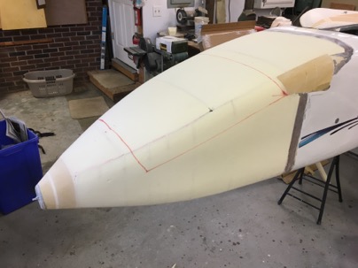
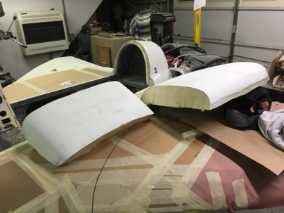
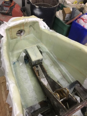
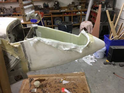
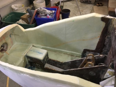
The top of the nose was cut off to allow access the the interior of the nose for glassing the inside of the nose and make it easier to create an access door.

wpid-IMG_3736-2015-12-13-17-26.jpg

I found it only took me 3 hours of glassing for this part of the nose interior.

wpid-IMG_3737-2015-12-13-17-26.jpg

wpid-IMG_3733-2015-12-13-17-26.jpg

One of the MAJOR concerns I have is drainage of rain water in the nose when the plane is parked outside. With the old nose, water collected in the front when it nose down and I always had to remember to clean the water out or I would end up with wet pants. I also need to design in low spots to help collect and drain the water from the moisture separator if I fly through rain (the nose up).

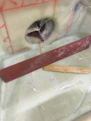
For the nose UP: A low spot was sanded into the foam prior to glassing to act as the main drain from the airbag when the nose is up in normal flight. A hole will be drilled for drainage at this end.

wpid-IMG_3756-2015-12-13-17-26.jpg

For nose DOWN: the floor is set flush with the inlet so when the nose is on the ground, any water in the lowest part of the nose will exit out the air inlet tube and drain any remaining water in the air box. There will be weep holes molded into the sides of the air box to let water out from the cabin into the air box and then out the nose. It is amazing, how sometime how the shit just works out.

A very slight depression in the forward part of the air box.

wpid-IMG_3758-2015-12-13-17-26.jpg

Looks nice now all cleaned up

wpid-IMG_3749-2015-12-13-17-26.jpg

Next my attention went to making a hatch for the nose compartment. I want this nose compartment to be truly useful for packing shit into and be easy to open/close so I will actually use it.

It will have a set of J-hinges to accommodate the drip rail and a lock actuated from the dash. There will be a molded compartment for storage and to protect the controls and wiring. I need some weight in the nose, and this area will be perfect for a small amount of baggage and tools.

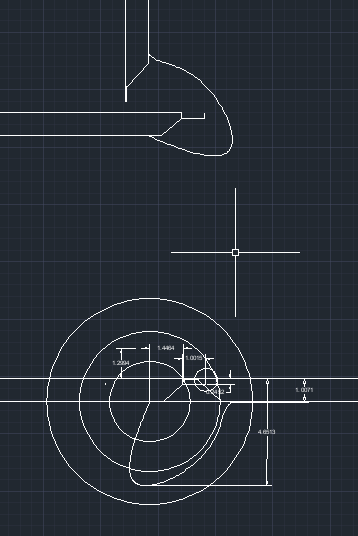
The operation of the J-hinge design was explored in audocad. Once I understood the dynamics of how it worked, It was easy to make the final design accommodate the restriction I had in the nose area.

wpid-ScreenShot2015-12-13at5.47.20PM-2015-12-13-17-26.png

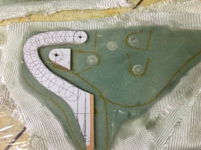
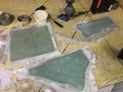
I machined some hard points out of 5/8” aluminum rod, inserted them into 1/8”: foam and glassed with 2-BID on each side.. Took less than an hour to make and glass.

wpid-IMG_3753-2015-12-13-17-26.jpg

Other pieces of foam was glassed for the airbox.

wpid-IMG_3750-2015-12-13-17-26.jpg

Next week should be fun. I will complete the air box, the nose door, reattach the top, attach the canard cover and do a final fill and finish. Exciting, because after I get the nose done, I can start some major ass kicking on the rest of the plane. I am ready to move on!

Dec 09 2015

Bumper installed

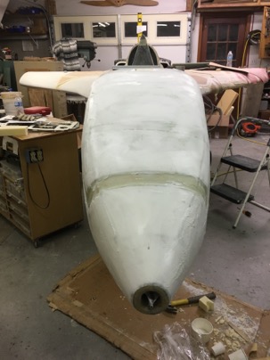
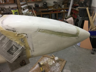
The top filled and sanded.
wpid-IMG_3716-2015-12-9-17-17.jpg

wpid-IMG_3715-2015-12-9-17-17.jpg

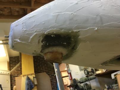
The block was glassed into place

wpid-IMG_3713-2015-12-9-17-17.jpg

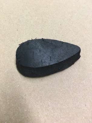
A chunk of old tire was found on the side of the road and shaped into an airfoil,

wpid-IMG_3714-2015-12-9-17-17.jpg

After glassing in, I covered the area with flox for additional strength. after I micro it one would never know it was there.

wpid-IMG_3717-2015-12-9-17-17.jpg

I had some spare time so I started on the belly board motor installation.

wpid-IMG_3720-2015-12-9-17-17.jpg

Dec 07 2015

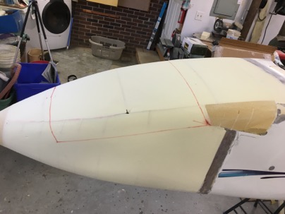
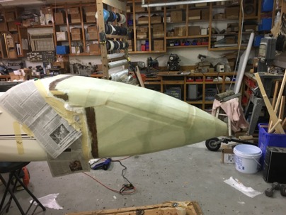
Nose is glassed

Today was a long 12 hour day.

After preparing the nose, it took 7 hrs to glass. I knew I should have started the next morning fresh.

Sanded and ready to glass.
wpid-IMG_3696-2015-12-7-16-19.jpg

wpid-IMG_3697-2015-12-7-16-19.jpg

Lesson:
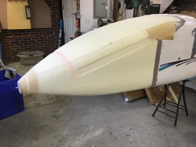
I made a huge mistake sanding recesses or taping the nose back together after cutting the top off. I thought I would save myself finishing time, but accomplished just the opposite. I should have just glassed, cut the top off and repaired. there would much less filling to do.
wpid-IMG_3699-2015-12-7-16-19.jpg

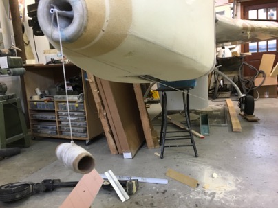
After running a string from the nose to the wheel I was shocked to find the lowest spot of the nose was located just behind the nose ring when the plane’s nose would be on the ground. This makes the bumper much further forward than I had hoped for. In all the modeling of the nose in Acad, I had not figured on where the nose would be when the plane is on the ground. Shit.

Lesson:
The longer the nose is the higher the WL of the pitot tube needs to be to move the bumper aft. It would be best to determine location (fore/aft) where you want the bumper mounted first then design around this constraint.
wpid-IMG_3702-2015-12-7-16-19.jpg

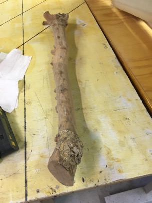
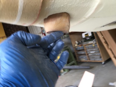
To make the bumper I was faced with three design criteria. Spread the load of the impact, protect the nose ring, resist abrasion of the asphalt. For abrasion, I selected a piece of Lignum Vitae wood I had acquired 22 years ago from a friend of mine. I planed to use for the bumper of a cozy 4 I was building at the time. It is nice to be a pack rat sometimes.

Lignum Vitae was once very important for applications requiring a material with its extraordinary combination of strength, toughness, and density. It is also the national tree of the Bahamas and the Jamaican national flower. It was used for bearings, propellor shaft bearing, wood turning, batons for Scotland Yard.

As an example: the compressible to Maple is 1450 and Lignum Vitae is 4500. It was like cutting aluminum on the band saw.
wpid-IMG_3704-2015-12-7-16-19.jpg

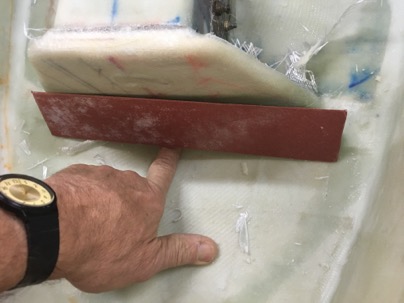
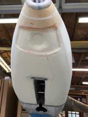
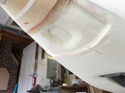
Fo spreading the load: A recess was sanded in the nose area to build a strap to hold the nose bumper in place and distribute the load of an impact if I do a gear up landing. It was made of multiple layers: 3-UNI glass, 2-carbon and 2-kevlar.

Lesson:
Had the pitot tube been higher, the further back the bumper would have been, and the less force there would be on the nose in the event of a gear up.
wpid-IMG_3709-2015-12-7-16-19.jpg

wpid-IMG_3705-2015-12-7-16-19.jpg

Protect the nose ring: The wood block fitted which will extend the bottom down by 1.5 inches. In the event of a gear up, thats how much wood would have to be ground off during the stop. It will be interesting to test, but hopefully it will be the next owner of the plane that does so.
wpid-IMG_3706-2015-12-7-16-19.jpg

I glassed a real heavy strap in this location to spread the load of an impact and take abrasion. I figure the more foam I can spread the load on (this is a solid block of pour foam in this area), the better it will absorb the shock of hitting the payment. The Wood should protect the nose ring from being damaged. In any event I hope to never have a gear up landing again due to the automatic extension system installed in the plane.

after the strap was glassed the entire nose was completed 7 hrs later it is 10:30 pm. Time head to bed.
wpid-IMG_3710-2015-12-7-16-19.jpg