Jan 02 2016

Air ducts

Ran into a BIG snag… my SCAT tubing (1.5”) is too big to go under my electric trim or elevator servo push rods. Shit!! I consider giving up on my idea of feeding the dash from my nose vent and just install NACA ducts on the side, but then came up with a better design. Custom made air ducts.

Actually they were very easy to make and 1/4 the weight of the scat tubing.

First transition ducts were made to covert the scat to rectangular. I calculated, a 3/4”x2” duct would have the same internal volume as my 1.5” round scat. The 3/4” height would fit nicely behind the push rods.

wpid-IMG_3890-2016-01-2-21-07.jpg

The transitions were floxed to the sides.

wpid-IMG_3891-2016-01-2-21-07.jpg

Duct tape was placed on the sides to protect the existing glass, and 2” urethane foam block was into 3/4” strips and 5 min glued to the sides.

wpid-IMG_3894-2016-01-2-21-07.jpg

wpid-IMG_3895-2016-01-2-21-07.jpg

The foam was covered with duct tape and glassed. Cleco/alignment holes prior to removal to ensure will be precisely lined up when I clean and reinstall the duct.

wpid-IMG_3901-2016-01-2-21-07.jpg

I tried using S glass roving on 1 BID for the glass for these ducts. The S glass did make them stronger but was a PITA to do. Next time I make a duct I think I’ll try 2 UNI at 45 dig angles. I think it would be as light and possibly stronger than what I made this time.

wpid-IMG_38981-2016-01-2-21-07.jpg

Dec 27 2015

Week Report #7

Week
                Week hours                Total hrs                Weekly average
1
2
3
4
5
6                24.6                                221                        37.0
7                13.1                                235.0                33.6
8

Dec 22 2015

Air sperator completed.

The design of the water/air operator was completed. First constructed out of cardboard, then luan plywood, then foam/glass

wpid-IMG_3836-2015-12-22-20-56.jpg

The funny shaped dividers was my idea of using the available space and configuration that I had to work with to get the water out. All the dividers direct the water to the drain which will go into the strut cavity. The tubes out the sides will allow me to direct air to the dash without going through the heater.

wpid-IMG_3837-2015-12-22-20-56.jpg

Dec 20 2015

Week Report #6

Week
                Week hours                Total hrs                Weekly average
1
2
3
4
5
6                24.6                                221                        37.0
7

Dec 19 2015

Hinges installed

The top was cleo aligned to the door

wpid-IMG_3810-2015-12-19-20-40.jpg

The hinges were installed

wpid-IMG_3812-2015-12-19-20-40.jpg

I now have nose door. I wanted to make a nice sized opening to all for travel storage in the nose. Moving the battery to the back spar removed 18 lbs of dead weight and 15 lbs of heavy battery cable. I’ll needs to moved my tools and extra junk to the nose for balance. A win-win in my book.

wpid-IMG_3816-2015-12-19-20-40.jpg

Dec 17 2015

I have a door

A recap of the last few days,

The door was cut open,

wpid-IMG_3793-2015-12-17-20-32.jpg

I selected a SILICONE seal for my weather seal. I like the long lasting flexibility of silicon, and it was about the right size.

wpid-IMG_3799-2015-12-17-20-32.jpg

I found a piece of luan ply wood was the exact height I needed. The seal was roughly 0.230” high, and I wanted a crush of about 30%. The luan was exactly 0.195” which is close enough.

wpid-IMG_3800-2015-12-17-20-32.jpg

The door was taped off,

wpid-IMG_3797-2015-12-17-20-32.jpg

Luan was cut into rings (corners) and straight pieces and hot glued to the seal area.

wpid-IMG_3802-2015-12-17-20-32.jpg

All was glassed, and the next morning,
wpid-IMG_3804-2015-12-17-20-32.jpg

I had a nice door seal molded into the top.

wpid-IMG_3806-2015-12-17-20-32.jpg

Dec 15 2015

Door construction

Glass was placed in each of the for corners of the door to all for cleo position alignment after the door is cut open.

wpid-IMG_3761-2015-12-15-20-26.jpg

I did not light the glass J hinges. The alum ones were twice the weight after drilling, but much stiffer.

wpid-IMG_3774-2015-12-15-20-26.jpg

Used a dowel to hold the hinges parallel and straight for bonding into the top.

        wpid-IMG_3775-2015-12-15-20-26.jpg

Dec 13 2015

Week report #5

Weekly hours: 42
Total hours: 197

Notes: it has been 3.5 weeks since I cut off the nose. My goal was 4 weeks to complete the nose work. Friday will be exactly 4 weeks. It will be a race to get it done by then.

Dec 13 2015

J-Hinge design

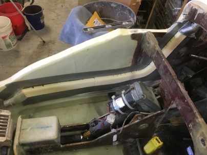
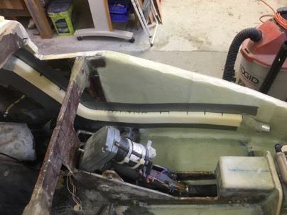
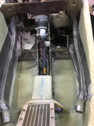
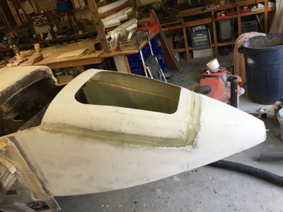
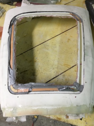
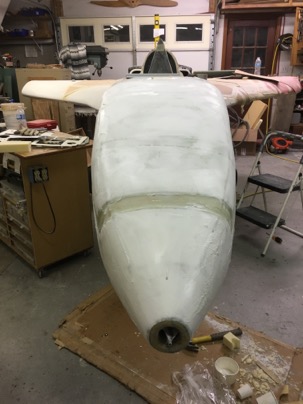
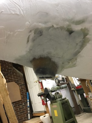
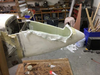
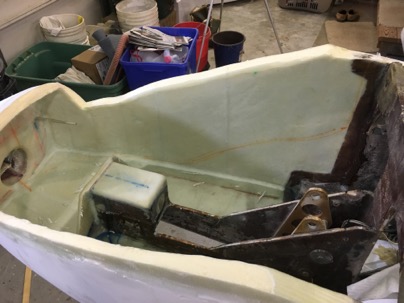
The top of the nose was cut off to allow access the the interior of the nose for glassing the inside of the nose and make it easier to create an access door.

wpid-IMG_3736-2015-12-13-17-26.jpg

I found it only took me 3 hours of glassing for this part of the nose interior.

wpid-IMG_3737-2015-12-13-17-26.jpg

wpid-IMG_3733-2015-12-13-17-26.jpg

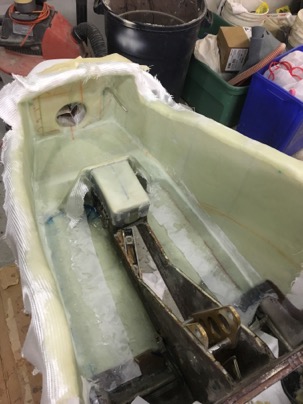
One of the MAJOR concerns I have is drainage of rain water in the nose when the plane is parked outside. With the old nose, water collected in the front when it nose down and I always had to remember to clean the water out or I would end up with wet pants. I also need to design in low spots to help collect and drain the water from the moisture separator if I fly through rain (the nose up).

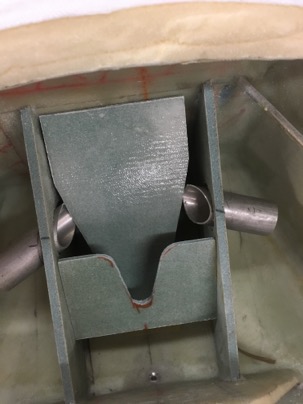
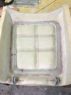
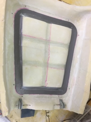
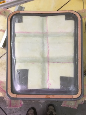
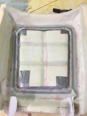
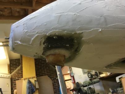
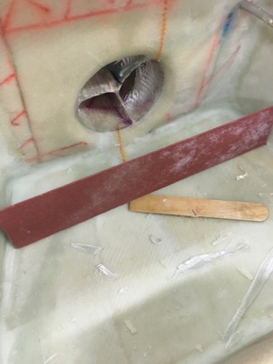
For the nose UP: A low spot was sanded into the foam prior to glassing to act as the main drain from the airbag when the nose is up in normal flight. A hole will be drilled for drainage at this end.

wpid-IMG_3756-2015-12-13-17-26.jpg

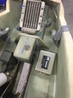
For nose DOWN: the floor is set flush with the inlet so when the nose is on the ground, any water in the lowest part of the nose will exit out the air inlet tube and drain any remaining water in the air box. There will be weep holes molded into the sides of the air box to let water out from the cabin into the air box and then out the nose. It is amazing, how sometime how the shit just works out.

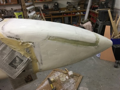
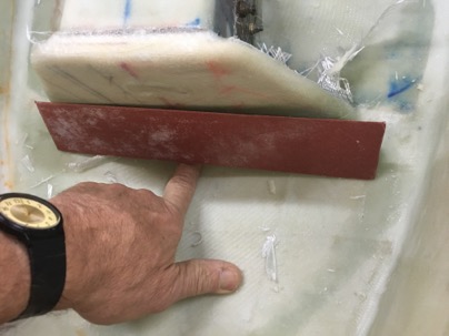
A very slight depression in the forward part of the air box.

wpid-IMG_3758-2015-12-13-17-26.jpg

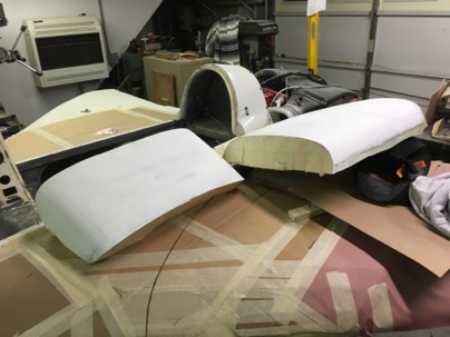
Looks nice now all cleaned up

wpid-IMG_3749-2015-12-13-17-26.jpg

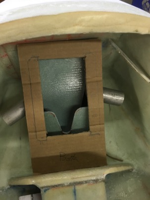
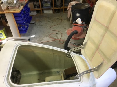
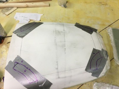
Next my attention went to making a hatch for the nose compartment. I want this nose compartment to be truly useful for packing shit into and be easy to open/close so I will actually use it.

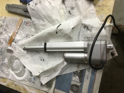
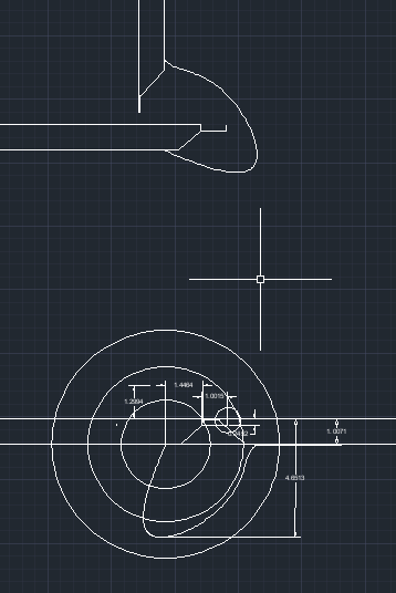
It will have a set of J-hinges to accommodate the drip rail and a lock actuated from the dash. There will be a molded compartment for storage and to protect the controls and wiring. I need some weight in the nose, and this area will be perfect for a small amount of baggage and tools.

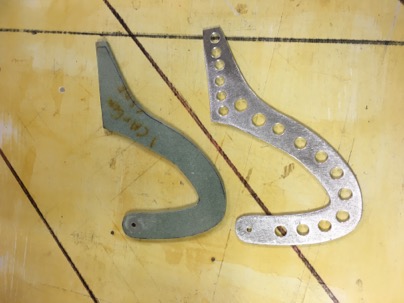
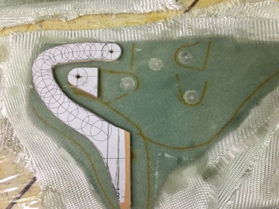
The operation of the J-hinge design was explored in audocad. Once I understood the dynamics of how it worked, It was easy to make the final design accommodate the restriction I had in the nose area.

wpid-ScreenShot2015-12-13at5.47.20PM-2015-12-13-17-26.png

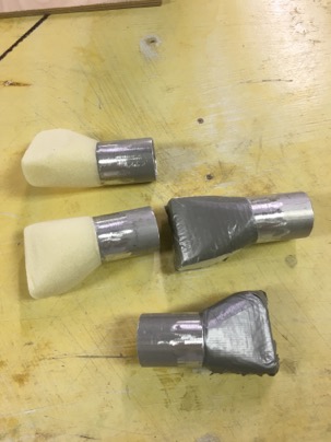
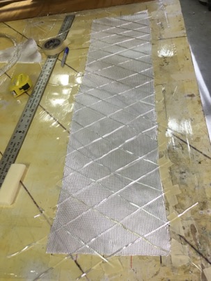
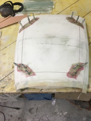
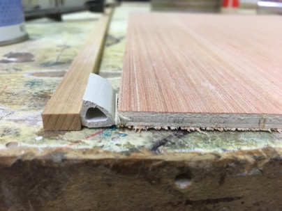
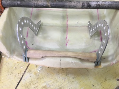
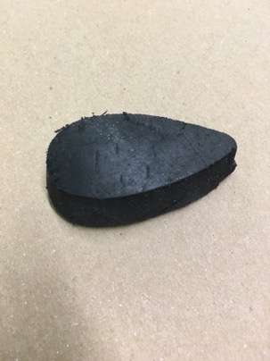
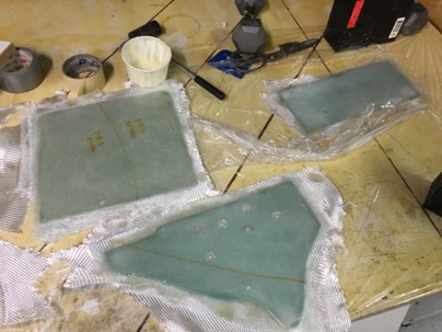
I machined some hard points out of 5/8” aluminum rod, inserted them into 1/8”: foam and glassed with 2-BID on each side.. Took less than an hour to make and glass.

wpid-IMG_3753-2015-12-13-17-26.jpg

Other pieces of foam was glassed for the airbox.

wpid-IMG_3750-2015-12-13-17-26.jpg

Next week should be fun. I will complete the air box, the nose door, reattach the top, attach the canard cover and do a final fill and finish. Exciting, because after I get the nose done, I can start some major ass kicking on the rest of the plane. I am ready to move on!

Dec 09 2015

Bumper installed

The top filled and sanded.
wpid-IMG_3716-2015-12-9-17-17.jpg

wpid-IMG_3715-2015-12-9-17-17.jpg

The block was glassed into place

wpid-IMG_3713-2015-12-9-17-17.jpg

A chunk of old tire was found on the side of the road and shaped into an airfoil,

wpid-IMG_3714-2015-12-9-17-17.jpg

After glassing in, I covered the area with flox for additional strength. after I micro it one would never know it was there.

wpid-IMG_3717-2015-12-9-17-17.jpg

I had some spare time so I started on the belly board motor installation.

wpid-IMG_3720-2015-12-9-17-17.jpg