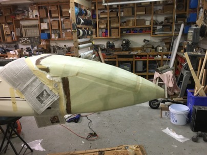
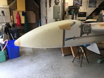
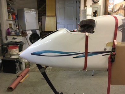
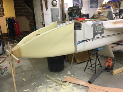
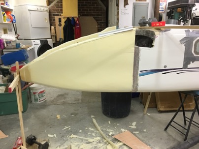
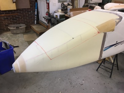
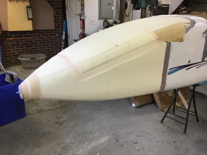
Dec 07 2015

Nose is glassed

Today was a long 12 hour day.

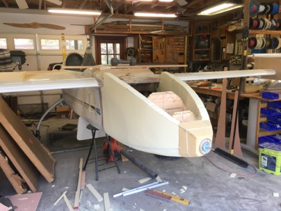
After preparing the nose, it took 7 hrs to glass. I knew I should have started the next morning fresh.

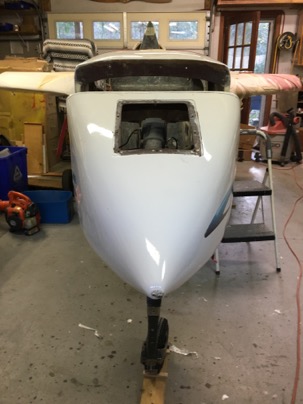
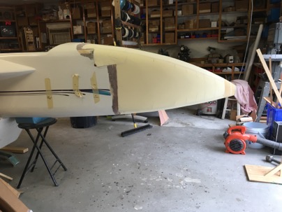
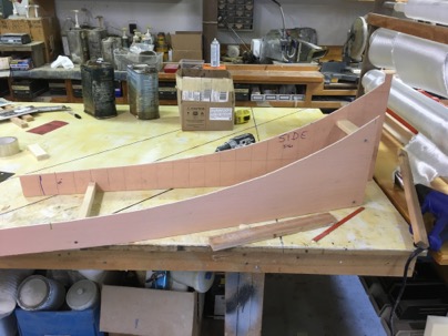
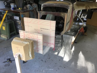
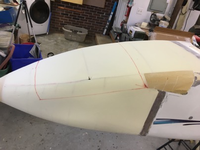
Sanded and ready to glass.

wpid-IMG_3696-2015-12-7-16-19.jpg

wpid-IMG_3697-2015-12-7-16-19.jpg

Lesson:
I made a huge mistake sanding recesses or taping the nose back together after cutting the top off. I thought I would save myself finishing time, but accomplished just the opposite. I should have just glassed, cut the top off and repaired. there would much less filling to do.

wpid-IMG_3699-2015-12-7-16-19.jpg

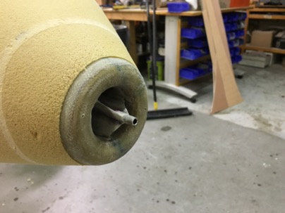
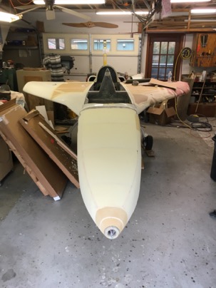
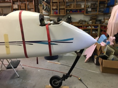
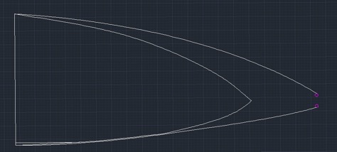
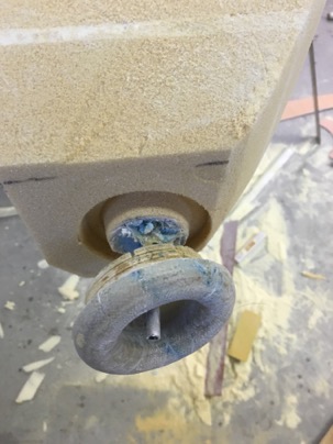
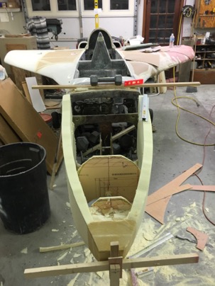
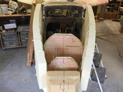
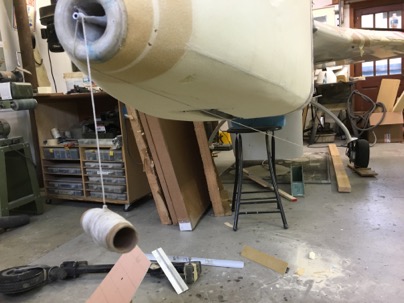
After running a string from the nose to the wheel I was shocked to find the lowest spot of the nose was located just behind the nose ring when the plane’s nose would be on the ground. This makes the bumper much further forward than I had hoped for. In all the modeling of the nose in Acad, I had not figured on where the nose would be when the plane is on the ground. Shit.

Lesson:
The longer the nose is the higher the WL of the pitot tube needs to be to move the bumper aft. It would be best to determine location (fore/aft) where you want the bumper mounted first then design around this constraint.

wpid-IMG_3702-2015-12-7-16-19.jpg

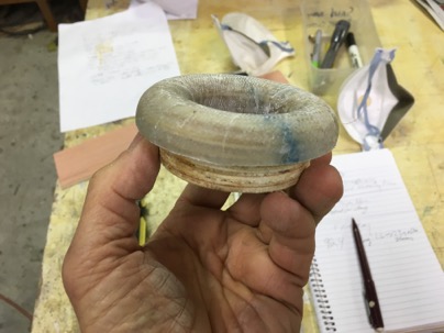
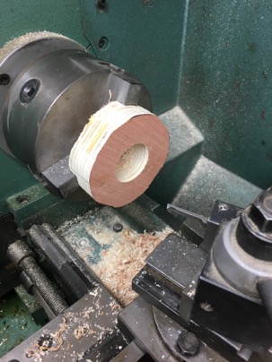
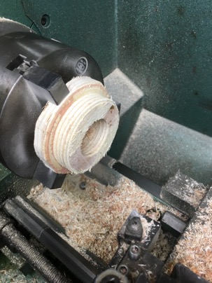
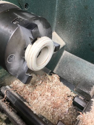
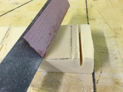
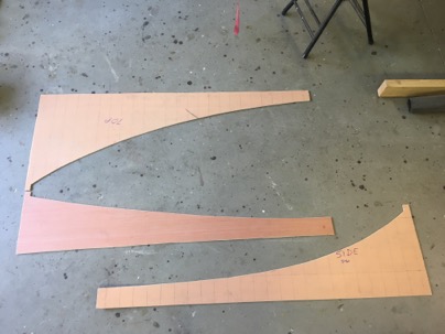
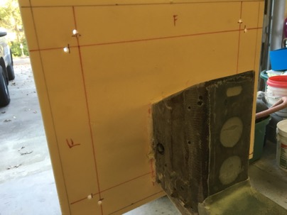
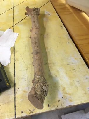
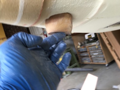
To make the bumper I was faced with three design criteria. Spread the load of the impact, protect the nose ring, resist abrasion of the asphalt. For abrasion, I selected a piece of Lignum Vitae wood I had acquired 22 years ago from a friend of mine. I planed to use for the bumper of a cozy 4 I was building at the time. It is nice to be a pack rat sometimes.

Lignum Vitae was once very important for applications requiring a material with its extraordinary combination of strength, toughness, and density. It is also the national tree of the Bahamas and the Jamaican national flower. It was used for bearings, propellor shaft bearing, wood turning, batons for Scotland Yard.

As an example: the compressible to Maple is 1450 and Lignum Vitae is 4500. It was like cutting aluminum on the band saw.

wpid-IMG_3704-2015-12-7-16-19.jpg

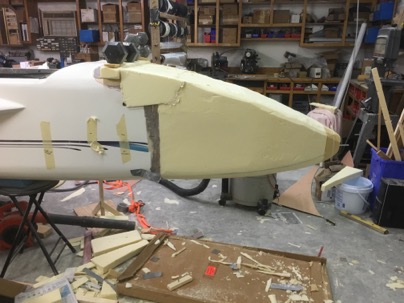
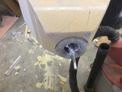
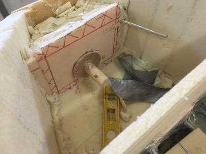
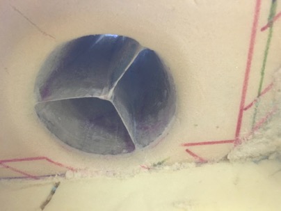
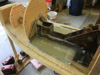
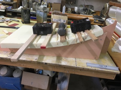
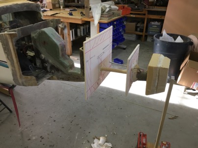
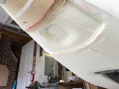
Fo spreading the load: A recess was sanded in the nose area to build a strap to hold the nose bumper in place and distribute the load of an impact if I do a gear up landing. It was made of multiple layers: 3-UNI glass, 2-carbon and 2-kevlar.

Lesson:
Had the pitot tube been higher, the further back the bumper would have been, and the less force there would be on the nose in the event of a gear up.

wpid-IMG_3709-2015-12-7-16-19.jpg

wpid-IMG_3705-2015-12-7-16-19.jpg

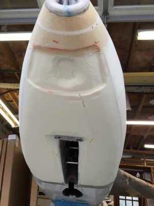
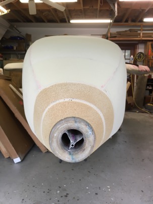
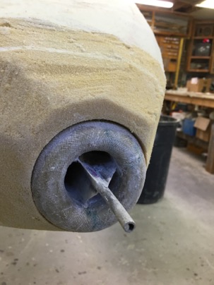
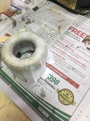
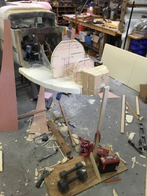
Protect the nose ring: The wood block fitted which will extend the bottom down by 1.5 inches. In the event of a gear up, thats how much wood would have to be ground off during the stop. It will be interesting to test, but hopefully it will be the next owner of the plane that does so.

wpid-IMG_3706-2015-12-7-16-19.jpg

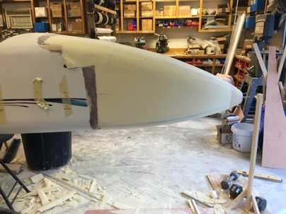
I glassed a real heavy strap in this location to spread the load of an impact and take abrasion. I figure the more foam I can spread the load on (this is a solid block of pour foam in this area), the better it will absorb the shock of hitting the payment. The Wood should protect the nose ring from being damaged. In any event I hope to never have a gear up landing again due to the automatic extension system installed in the plane.

after the strap was glassed the entire nose was completed 7 hrs later it is 10:30 pm. Time head to bed.

wpid-IMG_3710-2015-12-7-16-19.jpg

Dec 07 2015

Week report 4

Weekly hours: 43.7
Total hours: 155.4

I had given myself a month for the nose. So far is has been 1.5 weeks. It looks like it will take about 3 weeks to create the nose, glass, fill, sculpt the interior (and glass) fill and be ready for primer. Longer than I wished, but as good as I hoped for. Tomorrow I am read to lock the shape into place by glassing.

Dec 06 2015

The nose has emerged

After sanding for hours yesterday, and a bit today

wpid-IMG_3667-2015-12-6-22-33.jpg

the final nose look has emerged from the foam.

wpid-IMG_3680-2015-12-6-22-33.jpg

The pitot tube was shorted and came out as hoped for. It is now very ridged and looks good.

wpid-IMG_3693-2015-12-6-22-33.jpg

wpid-IMG_3686-2015-12-6-22-33.jpg

wpid-IMG_3432-2015-12-6-22-33.jpg

wpid-IMG_36901-2015-12-6-22-33.jpg

wpid-IMG_3430-2015-12-6-22-33.jpg

Seems really long to me (only 11” than initially) but it it is possible it looks strange because the canard is not installed at this time. But it does look much better than before.

wpid-IMG_3429-2015-12-6-22-33.jpg

wpid-ScreenShot2015-12-06at10.52.47PM-2015-12-6-22-33.jpg

wpid-IMG_3687-2015-12-6-22-33.jpg

All this work closely matches my design, but overall using Autcad was a waste of time (again).

Lessons learned:
Draw templates for the sides, bottom and top. Anything you want. Cut two templates out of each. Curve the foam (leave the templates on). Mount a bulkhead on a dowel, and put it on the front of the plane. Trim the bulkhead and add the bottom foam. Trim the bulkhead, add the sides and top. Carve. Easy, quick. I bet I could do a nose in less than a week including a custom air box. Ah, the price of learning is steep sometimes.

Eventually, due to the complex shape, I gave up using any templates and just sanded by eye and feel. It came out fairly good, I am pleased. Time to start glassing the structure to the plane..

wpid-IMG_3688-2015-12-6-22-33.jpg

Lessons learned.
You can see in the pictures I sanded down to the lines I cut in the foam for shaping. Had I left the foam in the jigs and attached them to the sides (better curvature), I would not have had to sand down so much material.

Dec 04 2015

Giving the bird the ring

After the ring cured, it was cleaned up,

wpid-IMG_3645-2015-12-4-22-07.jpg

small teeth (notches) were cut into the base

wpid-IMG_3647-2015-12-4-22-07.jpg

and it was just sanded into place open the nose. Gotta love the ease of working with this foam!! I inserted it as far as possible then floxed it into place.

wpid-IMG_3648-2015-12-4-22-07.jpg

With it installed, now I have a round ring to sand the foam of the nose down to. It will make for a nice smooth look.

wpid-IMG_3658-2015-12-4-22-07.jpg

The nose skeleton support dowel was removed, and the inlet tube foam was cleaned out to finally reveal If my idea worked for the inlet.

wpid-IMG_3655-2015-12-4-22-07.jpg

Yah!! I was left with an nice pitot tube in the nose

wpid-IMG_3674-2015-12-4-22-07.jpg

with a rounded inlet at both ends of the inlet tube for a smooth air transition into the separator box which I will have to assemble from 1/4” foam. and then glass into place.

wpid-IMG_3663-2015-12-4-22-07.jpg

Lessons learned:
This whole concept of constructing the inlet was a bit of overkill and time consuming due to my inexperience. Next time I’ll use urathaine foam, carve the entire inlet assembly (rounded corners, box, and cooler inlet) at one time. Split the box into for pieces. For the pitot tube, glass flat supports (1” wide) in two crosses when cured, re-assemble the box around the tubes, tape the outside of the box (leaving a bit of the support exposed, and glass. It would have been much faster, better quality and easier to do.

To install, after assembling the nose foam (base and sides, the box is put into place and pour foam locked the assembly into the nose. Less time, better quality job.

Dec 03 2015

Giving my plane a Nose Ring

One issue that has been dogging me is the inlet for the nose. I been trying to figure out an EZ to put a radius on the inlet for better airflow. Finally today I got the idea while in my Think Tank (my pool).

I am not a big fan of nose rings on humans, but decided, Tweety needs a nose ring.

The solution for my inlet is to create a ring for the nose which will slip over the existing inlet tube. The interference fit will allow me to flox it into place. The radius will be formed and glassed. When installed the tube walls will project out the end of the ring which I can then sand away. I will not have to do any complex glassing. Additionally, the ring will allow skin to be bonded to the ring really strong nose termination point. It will save me a bunch of time trying to form and glass a ring using foam.

I glued together a stack of trash 1/4 in luan plywood I was ready to throw away. A rough ring was cut a ring in the bandsaw,

wpid-IMG_3630-2015-12-3-17-52.jpg

40 minutes on the lath to shape the ring, The inlet tube is shaped at 7 deg and the ring inlet is cut at 10 deg. I will get exactly the 1.75” opening I was hoping for and allow for a nice interference fit.

wpid-IMG_3631-2015-12-3-17-52.jpg

Shaping the ring would had been faster if I could have found my freaking wood turning tools I used to use when turning spindles and bowls on wood lathe I sold. If I can’t find them, I’ll just go to Harbor Crap (harbor freight) and buy a cheap set. I may start turning more parts like this in wood or foam on the lathe.

wpid-IMG_3635-2015-12-3-17-52.jpg

20 minutes to glass

wpid-IMG_3641-2015-12-3-17-52.jpg

Boom, a nose ring in 1:40 minutes flat. Weight 2 oz.

Yuk, more sanding on the nose.
wpid-IMG_3651-2015-12-3-17-52.jpg

Dec 02 2015

Sides attched

Today the sides were fully attached, and ruff forming started.

wpid-IMG_3643-2015-12-2-17-50.jpg

wpid-IMG_3644-2015-12-2-17-50.jpg

wpid-IMG_3642-2015-12-2-17-50.jpg

Dec 01 2015

Forming the sides

Today I glassed part of the bottom. I thought it was an easy area to get to.

Learned:
In hind sight I probably should have waited to glass the bottom. The problem is water drainage. Since I sealed this part of the bottom, I have to have additional drain holes to accommodate the forward compartment.

wpid-IMG_3599-2015-12-1-17-26.jpg

I discovered an easy way to slot the foam and PRE-curve the sides. A little sand paper glued to a sanding board is an easy way to make slots in the curving the foam .

wpid-IMG_3625-2015-12-1-17-26.jpg

Then using the side templates,
wpid-IMG_3620-2015-12-1-17-26.jpg

It was easy to curve the foam and lock it in place with some pour foam. The great thing about curving the foam this way (slots) it is a good way to tell how far you sanded into the foam. When you sand and reveal a slot, you have gone deep enough into the foam and had better stop.

wpid-IMG_36021-2015-12-1-17-26.jpg

The sides had some spring back.

Learned:
Next time I would make the templates a bit MORE curved to allow for this characteristic.

wpid-IMG_3627-2015-12-1-17-26.jpg

The foam is being fitted to the sides.

Learned:
One should bond the sides to the templates (pour foam), to hold them in place and THEN attach them to the sides to lock them in position. They would be perfectly positioned with no spring back.

wpid-IMG_3618-2015-12-1-17-26.jpg

Learned:
Spent too much time planning the size of the bulk heads. I trimmed them when I fitted the sides anyway.

Nov 30 2015

Lower Nose skin attached.

Today the nose skeleton was attached and the bottom skin was installed.

I did all sorts of planning for where the skin would go on the bulkheads. Later I found it was a complete waste of effort.

wpid-IMG_3581-2015-11-30-17-19.jpg

The pitot tube was a great support for holding up the skeleton while I installed the nose floor.

wpid-IMG_3585-2015-11-30-17-19.jpg

wpid-IMG_3597-2015-11-30-17-19.jpg

Nov 29 2015

Week 3 Report

Hours worked: 39.9        
Total hours: 117.7

Average hrs/wk: 37.2

Notes: none

Nov 29 2015

Templates

It was somewhat of a play day for me making templates and shop organization.

While, I trust myself to carve the nose by eye adequately by eye, but I have an old saying to: “trust but verify”. It really didn’t take to long to lay out the templates on some 1/4 luan plywood and cut them out on the band saw.

The new shape of the nose is revealed.

wpid-IMG_3587-2015-11-29-20-22.jpg

On the templates I drilled hose near each corner. After attaching the foam walls, if I sand down to the point that I hit a tattle tail hole in the corner, I will stop shaping the corner at that point. It will give me a 1/2” wall thickness.

wpid-IMG_3590-2015-11-29-20-22.jpg

Tomorrow I plan to pre-curve the sides, bottom and top prior to assemble. Another interesting day ahead.