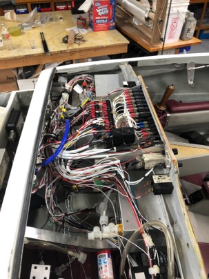
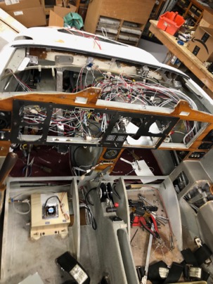
Today I started on removing the wiring from the plane. I wanted to preserved some of the original wiring (starter, ignition, etc).
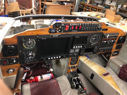
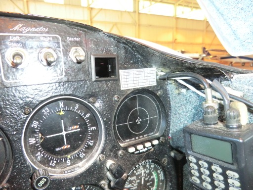
A nice looking instrument panel. I wold the entire panel to Spencer for a cozy 3 project he is working on.
I decided that I wanted to wire the plane differently and with the installation of the Dynon SkyView system, the harnesses will be completely different. I felt it was better to replace everything.
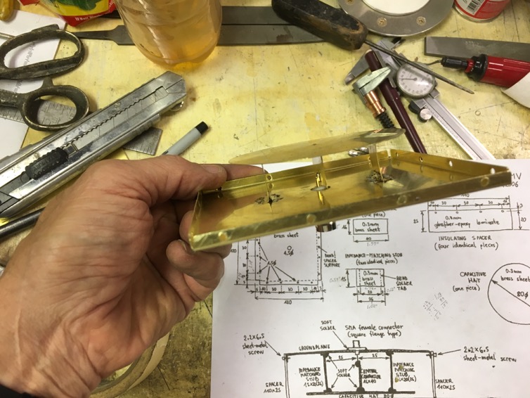
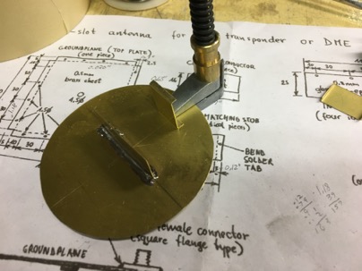
Yesterday I tried out a remarkable transponder/DME/ADS-b antenna I made. It is called an annular slot antenna. Very easy to build out of brass sheet stock. I never heard of this type of antenna. Apparently they are used extensively and most military aircraft use this type of antenna because they are no drag and totally flush on the surface.
Jack Wilhelmson told me about this antenna (he made one, but not tested) and gave me the drawings/materials, so I thought I would try making one for the plane.
Here is the fabrication drawing. Units are in MM, and be aware of the funny looking (European) “1” they look like a upside down V. If you look at the date of the drawing, you’ll see what I mean.
The write of of the antenna…
It was easy to solder it all together, and I had an extra BNC panel connector for the cable. It took about an hour to fabricate.
It is so simple to make I wondered if it would work at all given that it does not have a large ground plane, and is very weird looking.
TESTING:
To test the antenna, I temporarily ran a jumper cable from my existing transponder antenna location to the new antenna and went flying. At 3000 ft, I flew outbound from KCHS. At 25 miles, the transponder reply to ATC became intermittent. I was told by ATC that is about normal for most airplanes at that altitude which was very good initial test result in my mind. As soon as I banked around to return to the airport they immediately picked me back up again. So possibly, the signal was being shielded by the engine and the extensive ground planes installed in the aircraft.
I plan to leave the antenna connected in the plane for a while so I can test it on a real cross country flight to see if it performs as well as my existing external antenna. If it does, then I will definitely be using this design for my transponder/ads-b antennas in my future airplane. I would use it on my plane, but the entire bottom of the fuselage is painted with ground RF paint so I have to stick with my existing antennas.
This design will save a bunch of money, and I don’t have to worry about installing large ground planes for external antennas. Low drag transponder antennas are $80-$160 for a shark fin type. This one is no drag. One could hollow out the fuselage foam in the put a layer of glass to seal the foam and flush mount them on the interior of the plane and you would have no antenna exposer at all on the exterior.
Best of all you can build 2 of these antennas (for transponder and ADS-B) for about $25 with brass you can buy on amazon or a local hardware store. I am amazed I never heard of the design.
Here are some pictures of the build.
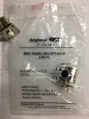
A BNC panel receptacle number 31-203-RFX about $4.00 Obtained at a local electronics store.
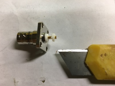
Trim off a bit of the unneeded insulator to help with the fabrication:
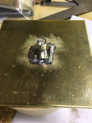
You could screw or rivet to hold the connector to the ground plane, I just soldered it.
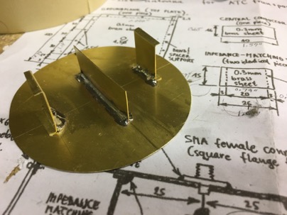
After soldering on the center rib, you attach the side supports. A cleco makes it easier to hold the rib in place.
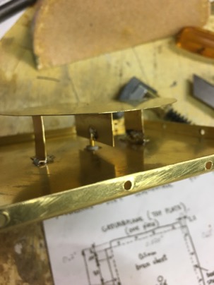
Attaching the electrode is easier if you pre-wet the areas with solder, then hold the pieces together to connect the parts. After the center electrode is done, solder the side supports to the ground plane.
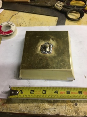
Done! I used a piece of card board to make a small enclosure case to protect the element and for testing.
I love to wire airplane. To properly wire, you must have the CORRECT tools for wiring.
One of the MOST important tools I have is my wire strippers. Why, because the wire we use in airplanes is VERY small, generally #20 or #22 wire and if you use the wrong stripper you can tear off the fragile wires of the core and reduce the current handling capacity of the wire.
YOU SHOULD NEVER USE ANYTHING OTHER THAN A MIL SPEC WIRE STRIPPER. NEVER
Two years ago, I bought a really Snap On teflon wire stripper at an airshow which cost me a whopping $200. The reason I paid so much is for this one reason…
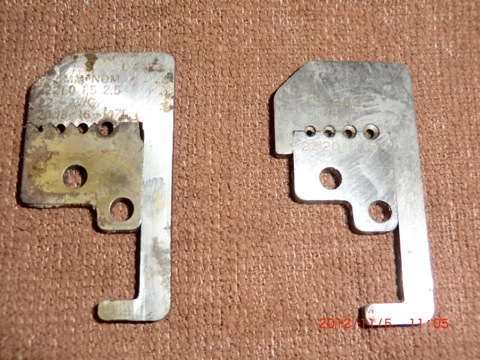
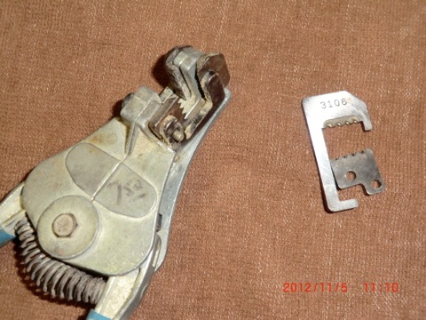
These little puppies. The blades. The one on the left is the standard blade you’ll find in tool boxes. The one on the right is a MIL spec blade found in the MIL SPEC stripper you should be using on aviation wire. The main difference is HOW it strips the wire. Almost everyone I have talked to don’t know the difference between a regular wire strip and the Mil Spec stripper.
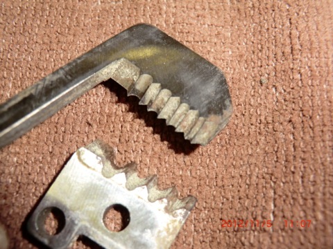
If you look closely at the blade of the “non-approved” stripper it has VERY sharp teeth which cuts the insolation and many times the wires themselves. There is only 16 threads of wire in the small gauge wire, and if you lose 2 or 4 of them, you reduce the current capacity of the wire and weaken the termination point.
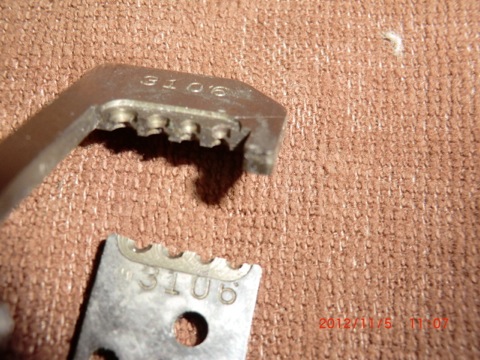
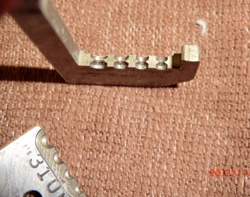
The MIL SPEC blades basically grip the insolation and tear it off. The wire openings have nothing shape on them to cut into the wire at all so you never cut the individual wires, you end up burnishing the wire bundle.
This is a better view of the inside of the blades.
I happened to have an old stripper (with the sharp cutting blades) laying around I picked up somewhere for $7.50. I remembered that I had and some replacement blades sitting around for 10 years which I bought at the Sun-N-Fun
“Fly-Mart” for about $15 but had never opened the package. I didn’t realize they were actually worth about $84 when I looked them up on line. So I thought why not use them.
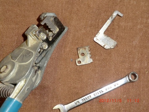
To make your own professional stripper, just order the blades of your choice, and replace the sharp ones
with the MIL SPEC blades and save yourself over $100. It took me less than 5 minutes.
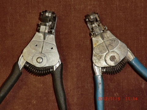
The stripper on the the left is my $200 Snap-On, the one on the right is the $22.50 stripper with the same blades that I put together from parts I had on hand.
If you want to save some $$$ just find an old Ideal wire stripper (for the frame) and order the PROPER Mil Spec blades on line.
Shortly after I received the replacement display module from Aircraft Extras for the fuel probes I wanted to test it right away. Low and behold, it had the same backlight issue the the first one I received.
CRAP, I thought that there has to be a reason both displays weren’t working properly. When I looked again at the wiring instructions I found a small jumper wire had not been installed to power the back light. Apparently, the first unit I received was working properly and it was my wiring mistake that caused the first one not to work. Immediately, I sent an e-mail to the designer apologizing for my mistake.
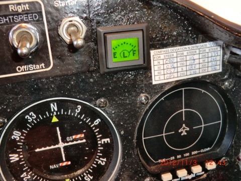
Since I had already pre-wired the plane, installing the electronics interface with the display was a quick operation.
installing the unit readout in the dash was also very easy as I already had a hole in it which had been used for the TRIO altitude hold system that I BETA tested. The hole was just there, not being used anyway. The display was exactly the same type and size as the TRIO, so the replacement of the alt hold switch/display with the fuel switch/display was a perfect swap out.
Now the bird has a nice little lighted display, that has 6 input, can easily be programed with different screens, low/high level alarms and can be installed in any EZ, old or new.
The fuel probes with this display is a perfect combination for canard flyers who wish to have electronic fuel probes and have not rewired their planes for the latest glass EFIS panels or electronic engine monitors.
FInally, after years of dreaming and working with 2 different companies to develop my system, it is now installed and working in my plane. Cant wait to calibrate the readouts and fly with it.
After I returned from Calif it took a few days to get my life back in order (as it always does when you are away for a while). Since I was planning to fly Tweedy up to PA for a birthday surprise on Nov 3 a goal was set of installing the noselift and higher compression pistons before I left Charleston. I wanted to have some steady run time to break in and seat the rings on the trip.
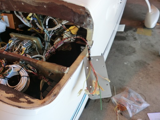
The noselift was a real challenge due to existing wiring and an electric panel which required relocating. The work took a few days longer than I would have hoped for, but in the end result it was worth the effort. Jack Wilhelmson gave me some excellent support for a few wiring questions and it worked great from the first power up.
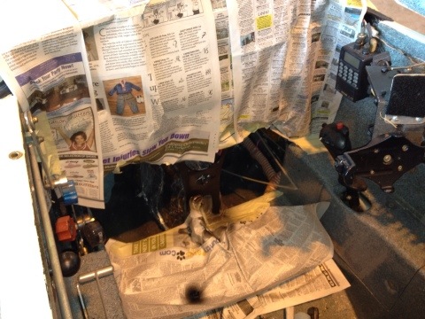
Here is just the beginning of the disassembly. Most of the electrics in the nose had to be removed and relocated. It ended up the 32 ahr battery had to be replaced with a smaller 18 aHr Odyssey battery due to space issues. I found the best price on the battery from Amazon which was almost $40 cheaper than ACS with free shipping! The battery change was actually helpful since the noselift weight about 8 lbs more than stock and the smaller battery compensates for the weight increase in the nose. The weight of the plane actually went down a few lbs and my CG didn’t change a bit.
I had to remove the old Dr. Curtis ratchet handle he used to sell. It worked great for 12 years.
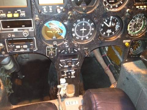
After the old system was removed, a nice paint job covered everything up. Surprisingly I didnt have to do anything to the panel other than remove the handle, sand it flush, paint and bond on the new electric panel. Glad something what easy on this install.
The wiring was easy to do and looks much better than my old 12 yrs inexperienced wiring job.
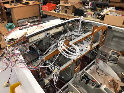
More wiring
Finished. Looking forward to testing the automatic extension system. It is also nice to be able to park the plane in the half way down position to move it around the hangar.
The wiring is essential complete, but now begins the process of carefully checking out each system prior to energizing to ensure I dont hopefully fry and expensive piece of equipment when I power it up. During the last few days I have been hard at work trying work out the electrical issues.
Overall the hardest problem to get rid of was electrical noise in the entertainment system. I hate noise in the headset and will go to great lengths to get rid of it. Noise problems are especially prevalent in composite planes and have spent over two days figuring out what was causing it and solving the problem.
I found the stereo input to the com panel is super sensitive to almost any kind of noise. I had to make TINY Delron bushing on almost all the connectors (even electrically isolated jacks) to prevent noise. This a a picture of a a fairly large one bushing I made as a “storage” jack for the stbd side 1/8″ stereo jack. I also had to replace and move some of the wires to eliminate the problem.
I even found out when the input jack is disconnected from the GPS, just touching it or having it bump into something will cause a buzz in the headset. To prevent this I made a bushing to park the jack into.
The jack was installed in the the stbd ball mount.
When the input plug is not being used, the I can insert it into the bushing which prevents any noise.
After taking the electronic equipment in and out the plane a number of time, I found I could completely remove all the electronics from the dash to have complete access to all of the wiring behind the equipment in about 10 minutes.
The EFIS panels (since they are custom machined and back set in the panel) have to removed from the front. They are disconnected, turned sideways and come right out.
I love the ability to quickly and easily remove them to make changes to the wiring.
After spend many frustrating hours trying to get the ADS-B properly configured and all the computer systems to talk to each other, I am finally happy with the wiring, and now it is time to tidy up the wiring with tie wraps, button everything up and start installing the interior.
While checking out the individual power circuits, I found a MAJOR mess up. When I originally designed the oil pan I had the fuel servo hanging up side down. Later I flipped it right side up due to space considerations. I didnt take into account the push-pull movement and I found out my throttle cable now moves in the wrong direction. Shit….
After thinking about it for a while I came out with a fix which works very well. I installed a SS shaft with a support bearing for the cable to attach to. This effectively reverses the movement of the throttle cable and now everything work correctly.
Today was also noteable as I finally powered up the EFIS panels.
It has been quite a chore in checking out the wiring and powering everything up. Just about every circuit has had some issue from missing grounds to connector broken wires issues which needed correction. Slowly everything is being checked out and put in service. Tomorrow it will be correcting an minor issue with the EFIS panels and starting on the radios which are the last to do. I want to have all systems up and operational by Friday or Saturday!