Category: Oil Heat

Jul 08 2020

Ram Heat Part 2 (Heating design)

Over the years I have tired EVERY way imaginable to heat the plane. I could tell you many stories of flying in cold weather. It is really a horrible environment to fly in. Gloves, hat, jacket, sweat pants or a snowmobile suite. It is so cold at altitude. ITS CRAZY that ytou can buy a cheap car with better heat than our planes.

Over the years:
I tried improving the plans exhaust heat system with additional contact area on the exhaust pipes and a fan. Worthless
I tied an electric heater. Drew 40 amps. Worthless
I tired a high pressure, recirculation air system. Fair

Engine oil pressure->external vernatherm->heater->engine return It uses a fan to blow air through the core.

This system worked ok. I had to duct the hot air to the pilot. I could keep the plane comfortable to about 20 def F OAT. At 15 deg F, OAT the plane was drown right cold due to the air leaks. Also I did NOT like the thought of high pressure oil in the cabin and the potential of a uncontrolled oil leak.

When I rebuilt my LongEZ, The driving factor for cutting off the nose was that, well I HATED IT, and the decision to incorporate a ram air opening and couple it with a heater using an oil pump to move the oil. I call it Low Pressure RAM Air heat. Using a ram air opening, i raise the cabin pressure to eliminate air leaks and additionally provides method of heating the incoming air without a fan. Simple and safe.

The air inlet on the nose of my EZ supplies both the heater and cold air supply vents for the dash. You can see some of the nose build process in my blog.

The LP RAM Heat concepts works exceptionally well. I can fly in any weather with no air leaks and in the coldest weather with jeans and light shirt. No air leaks, no fogging of the canopy. The coldest I have flown in is 0 deg F and I was still getting 110 deg F out of the heater. What I love is flying on a chilly day, like 45 def F. Turn on the system and supply just enough heat to be comfortable since the heat out put is adjustable. I love flying in cold weather now.

Note: Generally I measured a delta T across the cooler around 100+ def F. The temp of the oil supply from the engine at the heater is typically at 145 deg F.

I’ll be detailing the installation of RAM heat in my Cozy next.
Jul 08 2020

Ram Heat Part 1 (The discovery)

Ram Heat? What is it??

The discovery which started the process of Ram Heat began while flying home from Jacksonville, FL. It was raining, and naturally, I was getting little drips of water coming into the plane from leaks. The ones coming down the dash was especially annoying. Normally I just had air leaks, but in the rain its water leaks.

While watching the access door, to my amazement, I saw the water bubbling up from a tiny crack. Why? What as happening?

Eventually I connected an ASI to the static system of the plane an measure a -55 mph of air pressure in the cabin. If I opened the belly light, (which works exactly like a cow flap) I could increase the NEGATIVE cabin pressure all the way down to -120 mph!

YIKES, this the reason I have air and water leaks in the cabin. Its because the cabin is constantly at a negative pressure relative to the outside air.

Which leads to the question… Where does the negative pressure come from? I tired closing off and tapping ever opening I could in the plane with the exception of the GU torque tubes openings and the canopy. Up for a test flight, and guess what..? Still -50 mph pressure.

HUM, the problem must be the GU torque tube openings which are HUGE.

Back to the shop and I fabricated a set of offset GU torque tubes (you and see them and how to make a set at the website). I believe it is the first set ever made. Installed them, took the plane up for testing and the plane had not changed. Still -50 mph.

NOTE: I have come to believe that the cause of the low pressure is the 150 mph air flowing across the transverse opening in the plane, like turtle back or the front of the canopy. Just like blowing air across a soda straw. It creates a vacuum.

Solution 1. Because I was mainly interested in stopping the flow of rain water into the plane at that time (I used to travel a lot of rainy IFR), I knew I had to raise the cabin pressure. If the pressure is higher that static, then air would be pushed out of cabin and water could not enter.

I made an alternate air inlet door on the ram air duct of the engine (it was easy and convenient to do). In the rain, I would open the door, to allow air to be pushed into the cabin from the air inlet. It worked ver well to raise the cabin pressure cabin which completely stopped the entry of water. I could actually feel the air reversing from the eyeball vents. The major problem for this design is that it was VERY LOUD (from the engine breathing pulses) and I could only use it in the rain.

Conrolling cabin air pressure is essential in the plane. if your vent blows air into the cabin, you have a negative cabin pressure. Negative pressure means air and water leaks because your sucking it into the plane. The only realy way to stop air leaks is to raise the cabin pressure to positive.

Apr 23 2011

Engine Interference

Today was full of awwww shits….  now that the wiring is done, it is time to go back to working on the engine.  I need mod the oil cooler ducts and get some oil/fuel hose made up.  Shortly after starting some unforeseen miss matches showed up.

With the top cowl on I dont have enough clearance on the oil dipstick!  Shit the door wont close…


I ended up cutting the dip stick down to shorten it 3/4″

I also found the cowl hits on the front of #4 cylinder….shit.  I didnt want to cut up the baffling (dont have the time) or remake the #4 cylinder box, so I just bumped put the cowl.  Did want to do it but I had no choice. 


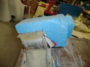
 After cutting the cowl out, I made a foam shape and glassed it in.  

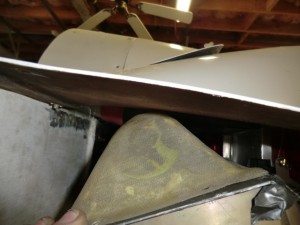
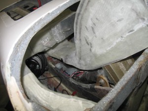
I also needed to make a new duct for the oil cooler since I changed the intlet and outlets.  This is the shape of the old duct.


You can see how the tubes no longer match up.

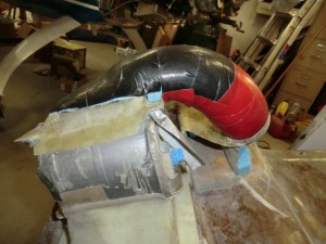
I felt it necessary to come up with a inlet tube which uses NO SCAT tubing, and still allows the easy removal of the lower cowl.

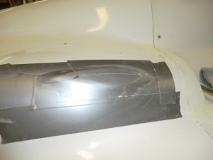
The cooler was encapsulated in foam and then carved it to the right shape.  It is then covered in duct tape (black and red) to get ready for the glassing.  This is the part of fiberglass work I really enjoy because it is very artistic. 

 Better get to glassing!

Oct 16 2009

Ooops!

Today Ken Laundry called me to discuss the oil heat system.  He was questioning the flow of the oil and the external vernitherm valve.   After opening my own website and reviewing the piping layout I realized that I had piped pPod wrong….  Oops!    It was piped where the hottest oil would first flow through the cabin then the external cooler, instead of the external oil cooler and THEN the cabin.   This would result in much hotter cabin heater temperatures.   It would have worked fine as piped but the goal is to keep the cabin heater as constant and as cool a temperature as possible.

After verifying mistake in the shop, I commenced to re-pipe the oil outlet of the engine.   Fortunately, it only required some piping which I had on hand and most of my work day.    Since it was I who  messed up I would never charge my customer for the cost of the rework.     The  import thing is that the system is properly installed. 

I spent a hour or two glassing  the back side of the NACA duct.    Not a great day, but it was successful on all accounts…..

Oct 12 2009

Hoses

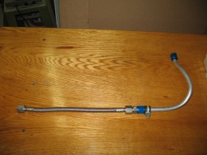
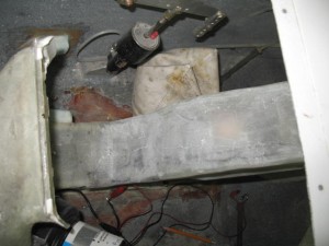
Today was spent getting ready for glassing.  I installed all the hoses I purchased last week which felt like a real step forward!  Had to order some Adel clamps to install the hose system.    This is the oil line.  It could have been made with a singel hose, but I prefer to minimize the use of hoses and replace as much as possible with hard tubing.  It will last the life of the plane and less chance of leakage.

IMG_3623

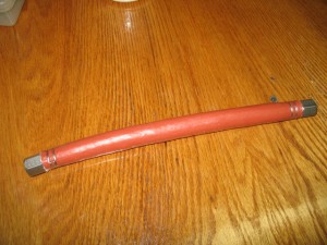
The fuel hose requires a covering of fire stop for safety reasons.

IMG_3626

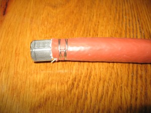
Really like the cheap little tool you can buy which allows you to use safety wire to make hose clamps instead of ….hose clamps.  I hate SCAT tubing and think hose clamps are ugly.   In this case they were not needed anyway, so why use them.

IMG_3629

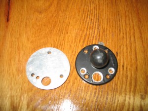
I have to make some support plates for the RAM mounts in the front seat.  I dislike wires showing unless absolutely necessary.  When you see a plane with lots of wires showing it is an example of poor planning.   Something was added after the plane was flying so the wires could not be submerged or hidden.    In pPod’s case, all components are known so there shouldn’t be later add-ons.   A hole was drilled in the RAM mount to allow the passage of the wires for the GPS.  The base will be heavily glassed into the the plan to all it to support any weight component (such as a Garmin 496 or 696 GPS) which can be attached to the mount.

IMG_3632

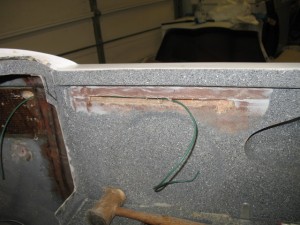
I tried tunneling through the foam to pull the wires though (to hide them), but gave up after a while in frustration so a slot was cut and the foam hollowed out.   When done, it will be glassed over for an invisible repair.    Isn’t fiberglass great stuff!

IMG_3633

Oct 09 2009

Catchup

I won a free copy of Windows 7 Ultimate for having a Windows 7 Launch Party at guess where….my house!!  It is a strange way Microsoft is introducing the new operating system.  So next week on the Oct 23, I have invited a bunch of friendsover to see the new operating system and have some burgers and beer.  Should be fun!  I have already received my party package complete with streamers, napkins, cards, and a bunch of other shit and my free software.  Actually, I am so enthusiastic with the software, it wouldn’t have taken much for me to have a party to show off the features anyway.  

Because of the party, I decided my computer desk need to be refinished.  I was a bit embarrassed with my grungy desk and it needed a new look if I was going to have guests over checking out the new software.  The refinishing came out great, but my computer was disassemble and posting wasn’t possible.   This will be a quick catch up on this week’s activities.

The instrument panel is now cut out.  I hope to start cutting instrument openings next week.

IMG_3589

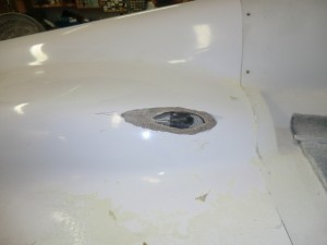
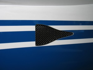
The submerged NACA scoop came out really nice.  All work was done from the inside of the plane so no repainting was necessary .

IMG_3604

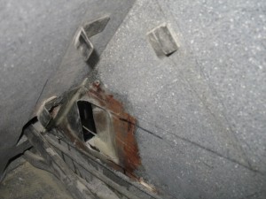
The inside part of the NACA.

IMG_3590

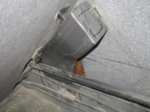
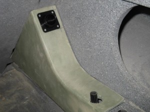
I made a duct from the NACA to the eyeball vent which will be installed on the the arm rest cover.  It has a little bit of a weird shape to clear the aileron torque tube.  I also will install a pilot controlled door in the the vent duct to allow for pressurization of the cabin when flying in rain or when extra ventilation is needed.

IMG_3592

This is how the vent will look in the back seat. 

IMG_3588

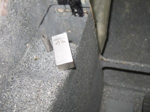
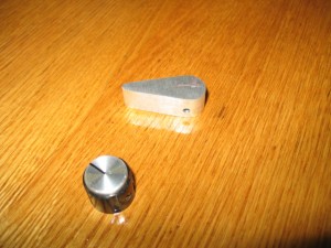
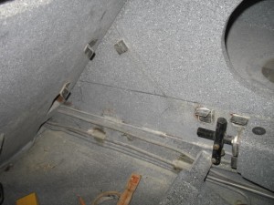
I was going to use a piece of Alum to make a control handle for the overboard oil heat door, but after I made it I found it weighted in at 15 grams. 

IMG_3597

I then remembered I am using the same style knobs for all interior electrics controls and can also use it for the heat door.  The knob only weight 8 gms for a savings of 7 gms over the Alum part and it works just as well.  It will give me a more consistent look for the interior.  I will recycle the alum part for an exterior canopy latch.

IMG_3598

The purge valve dump push/pull system is completed.   I have started checking out options for the wiring install.

IMG_3607

Sep 14 2009

NACA Vent

While working on the heating system installing screw plates  which will hold everything together, I found the nose lift cover I made would not come out with the duct system installed. 

IMG_3474

This is intolerable as I would hate to have to take the heating system appart just to service the nose lift.  I ended up splitting the cover to make servicing easier.  It is now been cut and re-glassed.  Tomorrow, I’ll install the nut plates to hold it together.

IMG_3475

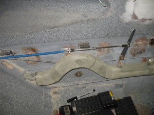
I also took appart the control linkage system in order to install the new NACA duct system for cabin presurization and ventilation.  I had to get access to the area so the tubes had to go….

IMG_3477

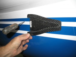
I plan to try and install the entire NACA duct from the inside of the plane to eliminate the filling and re-contouring of the outside of the plane.  This is going to be a challenge!  The ice pick is a locator which indicates where to mark and cut the outside of the plane.

IMG_3478

Total time worked today 2.6 hrs.

Sep 09 2009

Oil Heat System

Work continues on the heat system.  I tested the overboard heat dump yesterday when I assembled the entire duct system.  It worked GREAT!  The amount of air flowing out the valve was quite a bit and almost no air flowed to the back seat.  Just as I had hoped for. 
Heat valve being floxed to the interior wall

Heat valve being floxed to the interior wall


IMG_3433


Just a little more to do on the heat duct and then I’ll be working on the nose lift cover.


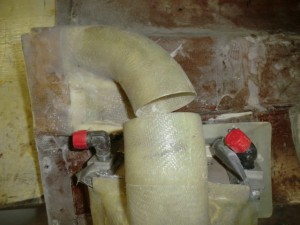
Heat duct system

Heat duct system