Aug 30 2010

Working on a sick friend

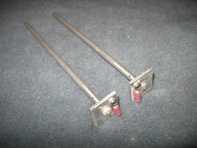
Yesterday, I stared making a new batch of fuel probes which have been selling surprising well.  Thats when I found Mr. Lathe was very sick…..  Yikes, he is one  of my best friends in the shop!  

Stop the presses, this is an emergency!!   

After downloading the wiring diagrams from the web, I spent hours trying to figure out how those dam low paid chinese gals wired him up.  At least the numbers were in english.  Imagine, hand drawings of the wiring!    Chicago Tools (Harbor Freight stuff)=Made in China junk (but the price is soooooo cheap).

After a few hours trouble shooting, I found a contractor had gone bad which has been ordered 2 day express from Calif.   I should be back up and going on Friday!  Woohoo!  

Replacing the contractor out (upper right box) from this wiring mess is going to be a challenge.  I think I would rather take part the dash of the car again.

After the trouble shoot bout with Mr. Lathe, I started back reassembling the engine.  It looks really good now.

Before I remount it on the engine, there was some firewall work to be done such as pulling wires through my bulkhead fittings.  What a mess!  At the top is a 95 db backup beeper.  It is great for scaring birds on landing and warning people at airshows to keep out of my freaking way!

This is a piece of 1/8″ copper tubing which will be for the manifold pressures sensor.  I prefer putting a copper tube though the bulkhead instead of just running a piece of rubber tubing.  I think it is safer and is less trouble some when removing the engine. 

I also stared working on the wiring of the engine information system area.  It is starting  to get fun now.    I love wiring!

Aug 29 2010

Grease Car Part 3, WVO Computer…..??

Work on the plane stopped for a few days while I worked on the car and a few other projects.  I plan to start back on the bird tomorrow… 

 After installing my WVO fuel tank the next step with the car was fixing a few nagging ventilation issues and designing/installating of my greasecar computer.  

The center vent for some reason stopped working which made cooling the car much more difficult, besides, I love having the wind in my face when I am driving or flying.    After a bit of investigation I found the vacuum diaphragm was ruptured on this vent controller.  Need to get it out and fix the dashpot. 

Such a simple looking thing… 


Yet I had to go to hell and back to get it out…… 


Now I know why they charge so much for Mercedes work.  I had to disassemble half my dash to get to the thing….  Of coarse it is in the worst place imaginable.  I guess that is why it failed…becuase I haven’t been spending much time with Sherman. 

After spending a few hours with my books on the AC system I also tried to reprogram my vent operation controller to do what I WANTED it to do.  


I basically gave up trying to re-educate Sherman.    Sometime there is no changing the way old people (or cars) work or think.  You just have to accept them for the way they are.   He get the AC  job done, in his own stately time in a crazy mix of opening and closing vents which I will never understand.    Fixing the vacuum dashpot seemed help a lot in cooling the car down on a hot summer day, so I am good for now. I also took the opportunity of some free time to wire up the sensors from the engine into the cabin for hook up of my custom designed grease car computer.  

The human brain is a wonderful thing.   What I could do so easily (watch the temp, turn on a switch, shut the system down) is really tough to design into a circuit….I would like to say my design worked like a champ, but I cant.

This is it… 


After frying some diodes and LED, I disabled a some of the features I worked so hard to build, and returned to basically what I originally had.  Shit…..  It should work as I planned it.  Although I spent a lot of time the last few days messing with this stuff, I can say it was a good thing because I’ll have to assemble some boards for the plane.  This project gave me some valuable experience in this direction. 

I plan next to take most of what was built apart, and then just enable small module of the “brain” to see if they work or fail and then trouble shoot the new circuit.   Assembling the whole thing, hoping it would work and then trying to trouble shoot is proved to be too much…..  

Maybe I should just stick to plane building…..

UPDATE: 

I have fixes the wiring (actually it was very simple) and updated the wiring schematic on the computer.  It has been working great for months!!

GreaseCar control system drawing (pdf file)

Enjoy!

Aug 23 2010

Grease car fuel tank

Yesterday started off with a quick 10 minute trip to a “Flyin Breakfast” at Monks Corner.  I helped a little with the food and setup, but mainly I just enjoyed a great early morning flight which was very nice. 

I wanted to show you the progress on the the construction of  Boeing 787 Dreamliner plant.  They are still adding to it.  The size is just immense!  I have to pass it to go to my hanger, so I see the progress on a regular basis.

Only about 40 people showed up at the breakfast.   Not many planes either as I think the weather (low clouds) may have put some attendees off.

I took the opportunity yesterday to finish off the oil tank part for my grease car.  I spent hours welding aluminum and finally thing I am starting to “get it” on welding this metal.  It certainly takes a lot of practice.   At least the welds are not coming like big blobs or melting through.  It takes a huge amount of current (175 A) and the TIG handle would get so hot I would have to let everything cool down ever 15 minutes.   The inside of the tank is built with a baffle and a coil of 5/8″ Al tubing which I can circulate hot water through for additional heating of the cooking oil if I ever decide to use it (cold weather ops).    I always like to plan ahead.

I have been using a 5 gal gas can for the last few months which conveniently fit into a well on the car for the cooking oil.  It held 5 gal of oil and gave me a range of about 110 miles.

The new tank holds 8 gals of oil and it also has a low level alarm which activates at 1 gal.   It looks a lot better than my red tank.

Speaking of red….  I wanted to paint the engine one color since the case was red and the accessory case was gray.  It took a lot of time to paint but the engine is again one color.  Tomorrow I’ll replace all the bolts with new ones .

The new look.   Kind of like it..

Aug 20 2010

Oil Pan is back

The oil pan is back from the machine shop.  They only charged $80 for machining the flange flat.  I hate oil leaks and I am sure it was worth the effort and money.

I have a long list of things to do from painting the engine accessory case to mounting ground blocks before I can put the engine back on the firewall.  It was really to my advantage to take the engine off the plane (took less than 1 hr) to gain access to the firewall and the front of the engine. 

This shows the firewall through bushings I made and installed.  Since they are high temp fiberglass products, they are floxed into the firewall.  They are nicely rounded on each end to prevent chafing of the wires and possible contact with the grounded firewall.    The starter cable has over 600 amps flowing through it and I want to make sure there is no possible way to contact the firewall, ground out, and start a fire. 

The bushings are 1″ long with a 1/2″ flange exposure into the engine compartment so I can put firestop on the end. In the unlikely event of an engine fire, the firestop will prevent fire/smoke from entering the cabin from the wire openings.

Aug 18 2010

Firewall Repairs

Today I put in some long hours and got a lot of things done. 

While sanding the engine mount to prep it for painting, I found an vent hole which had never been closed off because a support rod was in the way.  I just drilled a second hole, welded it closed, filled the tube full of linseed oil and closed it off.

Since I had the engine mount off, I took the opportunity to close off any unnecessary hole in the fire wall.  This was a big one the original owner had cut to allow for a DB-25 plug for the ignition system. 

I tired welding, but the metal is so thin I just couldnt get a stable arc, the fiberfax just vaporizes and blows holes in the weld.  Hum…what to do??

I decided to install cover plates over the holes with SS rivets.  It worked out much better. 

this plate closes off some holes used for the ignition system high tension leads.

There was a couple of big ones just below the cable pulley.   Closed off too.

I finished painting the engine mount.  Hopefully I’ll install it tomorrow if the paint is hard enough.

This is a one of four firewall bushing I machined out of a high temp fiberglass rod.  I am using these bushing to for all wires going through the firewall to prevent any contact (shorting) of the wires.  They are made long on the engine side so I can put a firestop sleeve over the exposed bushing and clamp it to the wires.

Aug 17 2010

Wiring started

Today was mainly spent ordering electrical supplies.  I want to make the instrument panel completely removable with cannon connectors so it can wired and operated on the bench.  The connectors are cheap, but the dam pins are very expensive.  I think that is how they really make their money…. little machined pins.

I have started to pull wires as I am waiting on the oil pan to be machined flat.  I cant put it on the engine just yet because the welding process warped it.  It rained all day in Charleston, so I couldn’t paint the engine mount either.

The headrest area behind the passenger is going to be very busy with wiring and instrumentation.  It will all be covered by a trim piece and a headrest.

The wiring from the engine monitor has 50 wires connected to it.  Each one has to be identified labeled and tested, then the drawings needs to be reviewed and corrected.  Tedious, but very necessary for future maintenance.   Actually I kind of think it is a bit of fun.  Sort of like doing a puzzle, sort of like doing artistry because it also has to look good when you are done too.

Aug 16 2010

Engine Mount Mod

I finally received the beautiful oil pan from Calif I designed.  When I started to bolt it up to the oil pan I found out the fuel servo was hitting the engine mount???  WTF????  After I checking it out I found out the fabrication company had welded on the mounting flange at 5 deg not 10 deg as I specifically directed in the manufacturing drawing I sent.  What to do.  I thought about machining the flange to 10 deg, but decided against that coarse of action as it caused other mounting problems with the servo and finally chose to modify the engine mount instead.

Here you see the fuel servo hitting the mount.  It still needs to move upward another 1/4″ to bolt on the oil pan…

The engine being removed from the mounts.

I chose to grind out part of the tube.  The 4130 tube is .050″ thick and I was surprised to see LOTS of linseed oil in it as is required to prevent internal rust.

I welded on a plate of 4130 steel .063″ to the mount after grinding away the cross tube.  It looks like it is ground at an angle but that is becuase the tube is tilted  when mounted.

The finished clearance.  I LOVE welding 4130 steel.  If you want to get good at welding, just weld Aluminum for a while.  It makes welding steel or stainless steel seem so easy a cave man can do it.   I now have 3/8″ clearence all the way around the fuel servo.  More than enough mount clearance.

Re-injecting about 1/4 cut of linseed oil back into the tube prior to sealing.  Tomorrow I’ll take the oil pan to the machine shop to have the mounting flange machined flat (should have been done in CA) as it warped during the welding process and repaint the engine mount. 

Total mod time 4 hrs.

Aug 15 2010

Fuel Probes Fiasco

I have been getting more orders for fuel probes almost exclusively through word of mouth.  Today I decided to mass produce a bunch of them to have an inventory of parts.  I have changed my original design somewhat to account for the spacers I am now getting from Princeton Probes.  It is supposed to save me building time.   What a fiasco!

I made about 75 bases which took about 3 hrs.  They looked great but unfortunately the holes ended up being too big even though I had drilled them severely undersized.  Shit….

They are now trash.   I even tried welding the tubes into the bases, but was not happy with the results.  Welding the tubes to the bases is still a possibility, but I can not use the ones I made.

I did end up making about 14 probe bases (4 of which are sold).

Sum total of 8 hrs of work…. two probes completed. 

My next step is to get some very small reamers and try liquid nitrogen to chill the tubes prior to insertion into the hot bases (creates a very tight bond of the two parts).   Might also try threading the tubes.   I hope that I can eventually come up with a better production methodology or I wont be able to make them at an affordable price.  It wont be worth my time….

Aug 14 2010

Visit to Twin Lakes, SC

Today Tony and I flew up to Twin Lakes, SC (S17) a fly in community with about 30 residents to visit with some builders as part of a field trip with the local EAA chapter.   It was a fun trip with LOTS of IFR time.  The entire trip to Twin Lakes was IFR (.9 hrs) and the clouds finally opened up enough to see the runway for a quick dash to the ground.   I had planned to go to Augusta, GA for an ILS approach if I had too.

There were lots of great project being worked on here.  Quite surprising for such a small air park.  The highlight was a 7/10 scale P-51 replica.

When I saw this nose art on the wall by R. T. Foster (a fantastic artist who I met at Oshkosh through my buddy Bob Becket),

I started talking to by builder and found out

he knew Bob, and West his business partner.  We had some really good friends in common.  What a small world it is….

About 2 pm the rain finally stopped, giving Tony and I enough of a window to fly back to Charleston. 

Flew though some rain and ended up doing a instrument approach back into CHS. 

I love flying IFR.  The weather is challenging and increadiably beautiful.