Jul 15 2020

Pitot – Static System

Today the pitot/static system was completed.

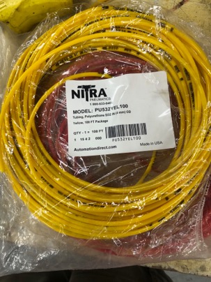
I have a bit of a different idea about plumbing the pitot/static system. I like to use .093 polyurethane 4mm tubing (yellow-static, red-pitot) for my instruments.

IMG_1612-2020-07-15-23-34.jpg

This tubing has a very small ID diameter and is very tough. Since there is no air flown in the static and pitot system one can use a very small tube to transmit the information. I think using 1/4” tubing for these system is way overkill and completely necessary.

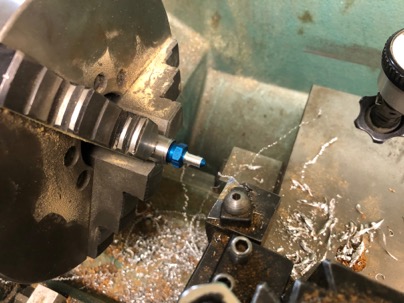
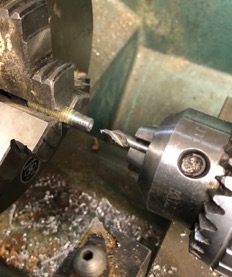
I have made adaptors to use with 1/8 NPT to 1/8 in tubing, but I found it easier to just by a 1/8” -2 flare fitting and machine the nipple down to .125”. Easy.

IMG_1194-2020-07-15-23-34.jpg

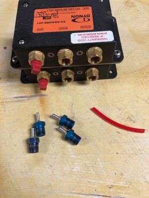
I found a deal on Ebay for 6 AN4-2 fitting for $15. Saved me a bunch of work and they look nice.

IMG_1195-2020-07-15-23-34.jpg

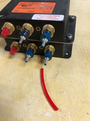
Installed in the AHARS.
IMG_1196-2020-07-15-23-34.jpg

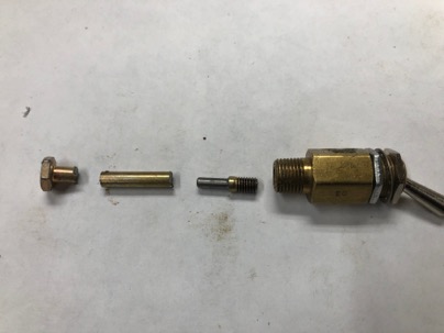
A small adaptor had to be made for the alternate static air mechanical switch using a AN-3 bolt as stock.
IMG_16081-2020-07-15-23-34.jpg

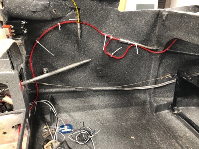
I like using the different colored tubing as it make identification of the systems very easy. Here is the Pitot tubing in red.

IMG_1614-2020-07-15-23-34.jpg

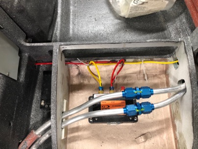
The AHARS is plumbed.

IMG_1613-2020-07-15-23-34.jpg

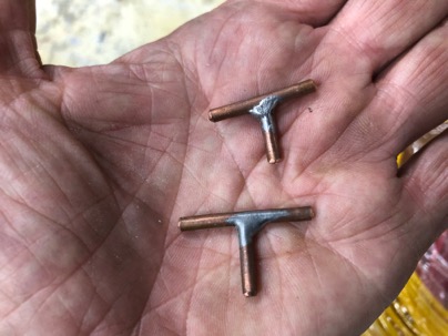
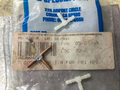
For the T-fittings, I used some 1/8” copper tubing and soldered a tube it. Very easy to make and very robust. The tubing is very hard to stretch over the 1/8” fittings and will never come off.

IMG_16161-2020-07-15-23-34.jpg

You can buy these nylon tee fitting from ACS PN 05-01053 but I found my home make ones work great too. The copper ones are a little heaver, but it is easier to install the tubing on them than the nylon one. If necessary you can heat the tubing up to stretch it over the fittings. It will shrink back done to tightly grip the fitting when it cools down.

IMG_1619-2020-07-15-23-34.jpg

Jul 15 2020

Dynon Cable Tester

DYNON Circuit Tester

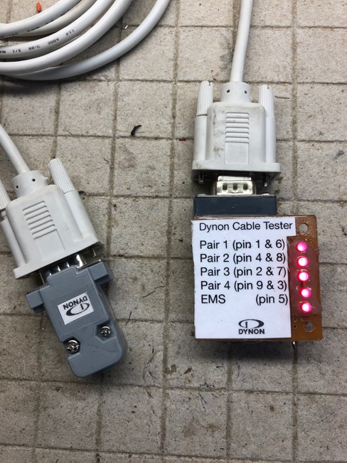
I am planning to make all my own wiring harness for the Dynon system. To save fabrication and trouble shooting time, I made a simple cable tester. This way I can test all the DB-9 connectors as I add them to the harness to ensure the wires are connected properly and the phasing of the twisted pairs is correct.

IMG_1621-2020-07-15-22-00.jpg

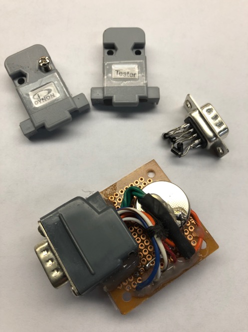
The tester which uses a small 3 volt battery to power the LED’s and some diodes to ensure the phasing of the coupled pairs. The label was printed out on paper and glued to the circuit bard with spray adhesive.

IMG_1625-2020-07-15-22-00.jpg
http://nickugolini.com/blog/wp-content/uploads/2020/08/PLTcf1e.tmp-2020-07-15-22-00.pdf

Jul 08 2020

Ram Heat Part 2 (Heating design)

Over the years I have tired EVERY way imaginable to heat the plane. I could tell you many stories of flying in cold weather. It is really a horrible environment to fly in. Gloves, hat, jacket, sweat pants or a snowmobile suite. It is so cold at altitude. ITS CRAZY that ytou can buy a cheap car with better heat than our planes.

Over the years:
I tried improving the plans exhaust heat system with additional contact area on the exhaust pipes and a fan. Worthless
I tied an electric heater. Drew 40 amps. Worthless
I tired a high pressure, recirculation air system. Fair

Engine oil pressure->external vernatherm->heater->engine return It uses a fan to blow air through the core.

This system worked ok. I had to duct the hot air to the pilot. I could keep the plane comfortable to about 20 def F OAT. At 15 deg F, OAT the plane was drown right cold due to the air leaks. Also I did NOT like the thought of high pressure oil in the cabin and the potential of a uncontrolled oil leak.

When I rebuilt my LongEZ, The driving factor for cutting off the nose was that, well I HATED IT, and the decision to incorporate a ram air opening and couple it with a heater using an oil pump to move the oil. I call it Low Pressure RAM Air heat. Using a ram air opening, i raise the cabin pressure to eliminate air leaks and additionally provides method of heating the incoming air without a fan. Simple and safe.

The air inlet on the nose of my EZ supplies both the heater and cold air supply vents for the dash. You can see some of the nose build process in my blog.

The LP RAM Heat concepts works exceptionally well. I can fly in any weather with no air leaks and in the coldest weather with jeans and light shirt. No air leaks, no fogging of the canopy. The coldest I have flown in is 0 deg F and I was still getting 110 deg F out of the heater. What I love is flying on a chilly day, like 45 def F. Turn on the system and supply just enough heat to be comfortable since the heat out put is adjustable. I love flying in cold weather now.

Note: Generally I measured a delta T across the cooler around 100+ def F. The temp of the oil supply from the engine at the heater is typically at 145 deg F.

I’ll be detailing the installation of RAM heat in my Cozy next.

Jul 08 2020

Ram Heat Part 1 (The discovery)

Ram Heat? What is it??

The discovery which started the process of Ram Heat began while flying home from Jacksonville, FL. It was raining, and naturally, I was getting little drips of water coming into the plane from leaks. The ones coming down the dash was especially annoying. Normally I just had air leaks, but in the rain its water leaks.

While watching the access door, to my amazement, I saw the water bubbling up from a tiny crack. Why? What as happening?

Eventually I connected an ASI to the static system of the plane an measure a -55 mph of air pressure in the cabin. If I opened the belly light, (which works exactly like a cow flap) I could increase the NEGATIVE cabin pressure all the way down to -120 mph!

YIKES, this the reason I have air and water leaks in the cabin. Its because the cabin is constantly at a negative pressure relative to the outside air.

Which leads to the question… Where does the negative pressure come from? I tired closing off and tapping ever opening I could in the plane with the exception of the GU torque tubes openings and the canopy. Up for a test flight, and guess what..? Still -50 mph pressure.

HUM, the problem must be the GU torque tube openings which are HUGE.

Back to the shop and I fabricated a set of offset GU torque tubes (you and see them and how to make a set at the website). I believe it is the first set ever made. Installed them, took the plane up for testing and the plane had not changed. Still -50 mph.

NOTE: I have come to believe that the cause of the low pressure is the 150 mph air flowing across the transverse opening in the plane, like turtle back or the front of the canopy. Just like blowing air across a soda straw. It creates a vacuum.

Solution 1. Because I was mainly interested in stopping the flow of rain water into the plane at that time (I used to travel a lot of rainy IFR), I knew I had to raise the cabin pressure. If the pressure is higher that static, then air would be pushed out of cabin and water could not enter.

I made an alternate air inlet door on the ram air duct of the engine (it was easy and convenient to do). In the rain, I would open the door, to allow air to be pushed into the cabin from the air inlet. It worked ver well to raise the cabin pressure cabin which completely stopped the entry of water. I could actually feel the air reversing from the eyeball vents. The major problem for this design is that it was VERY LOUD (from the engine breathing pulses) and I could only use it in the rain.

Conrolling cabin air pressure is essential in the plane. if your vent blows air into the cabin, you have a negative cabin pressure. Negative pressure means air and water leaks because your sucking it into the plane. The only realy way to stop air leaks is to raise the cabin pressure to positive.

Jul 07 2020

Switch bushing done. Panel ready for wiring

I like constancy on my dash. I ordered some knobs for rotary switches from Grand Rapids Technologies which match the knobs used on the dynon system.

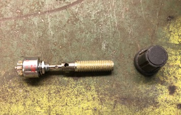
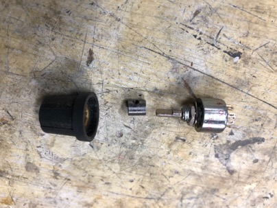
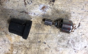
One of my rotary switches has a 1/8” shaft and the knobs are made for 1/4” shafts. Therefore I had to make a small bushing adaptor.

IMG_1574-2020-07-7-19-20-1.jpg

An old bolt is the perfect size to make a bushing.

IMG_1575-2020-07-7-19-20-1.jpg

IMG_1576-2020-07-7-19-20-1.jpg

IMG_1577-2020-07-7-19-20-1.jpg

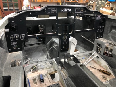
I also had a chance to fit the dash to the panel to ensure all equipment will fit the openings. Now it is time to install all the hardware and equipment to being wiring the plane. I love wiring!

!IMG_1579-2020-07-7-19-20.jpeg

Jul 07 2020

Zip Loop Update

I have had a few requests for more information about making zip loops. I LOVE these little things. They are absolutely essential for securing wire, tubing almost anything you want to support to the fiberglass structure of the plane. I have over 150 in my LongEZ and over 100 in my cozy and really help to secure just about anything you can imagine in the plane.

Light weight, easy to make ZL’s make it easy to attach almost anything to your fiberglass structure. They are also easy to remove. Just apply a little heat from a heat gun, and the epoxy softens and you can remove them.

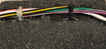
For attaching wires.
IMG_1566-2020-07-7-08-24.jpg

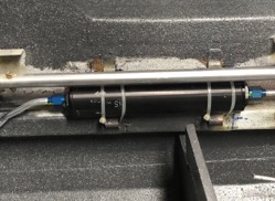
For attaching anything. Zip loops (5/8” wide) to secure my fuel filter.
IMG_1569-2020-07-7-08-24.jpg

You can also bond them directly to aluminum (such as holding wires to your engine) using a high temp JB weld epoxy.
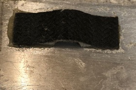
IMG_1567-2020-07-7-08-24.jpg

ZL’s are very light weight and extremely strong. I built test rigs and have tested them to over 75 lbs of pull (tensile strength) before failure.
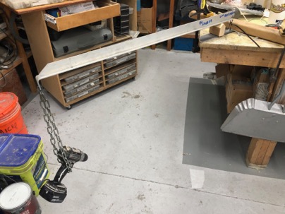
IMG_1240-2020-07-7-08-24.jpg

In testing has proven that NO zip tie (or even doubling up the strongest zip tie I have) is as strong as the ZL.
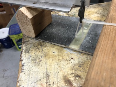
IMG_1232-2020-07-7-08-24.jpg

To test the ultimate pull strength I had to use nylon rope.
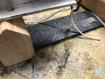
IMG_1237-2020-07-7-08-24.jpg

I discovered the ZL will always tear through the loop before separating from the base IF you bond them directly to sanded fiberglass.
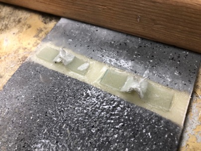
IMG_1236-2020-07-7-08-24.jpg

If you bond them to a painted surface the attachment strength of the ZL will only be as strong as the surface material strength. This shows how the ZL pulled the clear coat off the base coat.
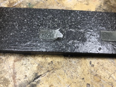
IMG_1239-2020-07-7-08-24.jpg

It is always recommended that you plan for your general wire or tubing runs and glue the zip loops in the appropriate locations so they are bonded directly to the fiberglass structure prior to painting the interior of the plane. Wherever possible, I always lightly sand the surface of the plane prior gluing the ZL..

The jig to make the ZL is easy to make. My gig is made from scrap wood with two strips of 1/4” x 1/8” Al rails screwed to the surface.
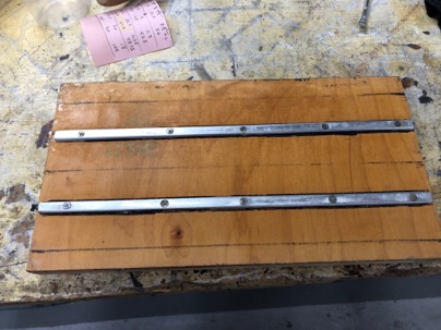
IMG_1500-2020-07-7-08-24.jpg

Untitled_Artwork-2020-07-7-08-24.jpeg

Guide lines on each side of the rail so I know how far I need to place the glass when doing the layups.
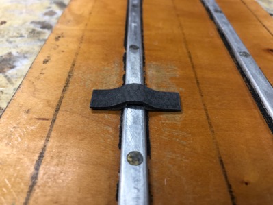
IMG_15022-2020-07-7-08-24.jpg

Procedure for making the ZL.
1. Wax the gig a few times
2. Use a small amount of flox to fillet each side of the AL rail to allow the glass to lay smoothly lay over the rails.
3. Apply 3 layers of BID or 2 layers of carbon over the rails You can make them ZL from scrap glass and extra epoxy you have from a layup. Use your excess glass/epoxy from a layup to make a few or as many ZL’s as you have material for. You can use West or a structural epoxy. Either works fine.
4. Apply peel ply to the surface.
5. Let cure. NOTE* I like to place my gig in a bag and pull a vacuum on the layup to remove excess epoxy.

After cure, remove the layups from the jig, remove the peel ply and sand the flat back side to roughen the surface and remove the wax. Its easier to do it now, than to sand the individual ZL’s.

ON BANDSAW

  1. On the back use a pencil to mark a line 1/2” on each side of trough, and saw off the excess glass with the band saw. I use a hack saw blade (its 1/2” wide) as a straight edge guide for marking the cut line. You should now have a strip about 1 1/4” wide and the length of your gig.
  2. Make a simple guide gig to hold the strips 90 deg when cutting the individual ZL.
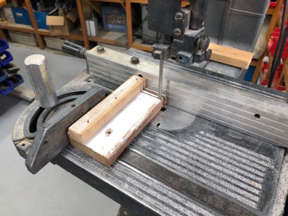
IMG_1503-2020-07-7-08-24.jpg

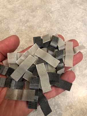
Cut the ZL to the desired length (using the fence of the bandsaw).

Generally I like to cut my ZL’s about 1/2” wide. I also make them from 1/4” (for just a few wires), to 5/8” wide if I have something heaver that I want to mount such as heavy cables, or a filter. IMG_1568-2020-07-7-08-24.jpg
Jul 04 2020

Panel ready for installation

Today was spent preparing the plane structure for accepting the instrument panel.

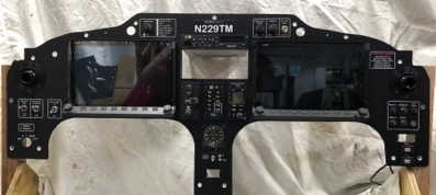
The panel was temporarily installed and all the switches and equipment was installed to make sure the clearances were ok in the old instrument panel.

I really like the way the panel came out and look forward to flying with it.

IMG_1538-2020-07-4-10-35.jpg

IMG_1541-2020-07-4-10-35.jpg

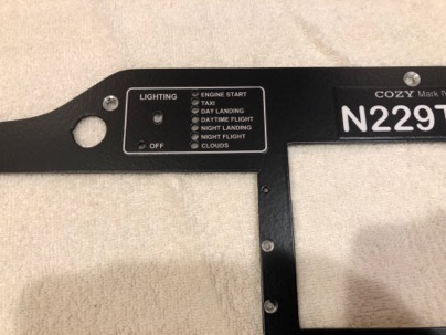
I forgot to add the passenger warning, so I called the vinyl print shop and they printed this out for me the same day. Using vinyl lettering really speeds up the process of fabricating the panel.

The lettering came out really nice and was really easy to do.

IMG_1549-2020-07-4-10-35.jpg