Category: Uncategorized

Mar 02 2021

Downloading Seattle Avionics Maps with an Apple computer

I am an Apple computer user. If you wish to use the Seattle Avionics maps for your GRT or Dynon system your faced with a problem. The ChartData program ONLY works with a Windows computer. The Seattle Avionics suggested technique for downloading to an Apple computer is IMHO totally unworkable.

For the last few years I have been using an old windows laptop which always given me problems using the ChartData program. Partial downloads, corrupted files, inability to download to two USB sticks at the same time.

Out of frustration, I first decided to buy a new (cheap) windows laptop for the sole purpose of downloading maps. Then I remembered there is a program called Parallels which allows the user to load Windows on the Apple computer and operate in a virtual environment.

I downloaded Parallels (free trial) which included Windows on my Apple computers (both a Mac and Apple Air laptop) for testing and finally the ChartData program and within minutes began downloading the Dynon chart data without a bit of problem. The first time ever that I had no issues with the downloads.

I would suggest if you wish to download ChartData Maps for your EFIS on a Apple computer then Parallels for the Mac (cost me $49) is a perfect alternative to using a Windows computer to download your maps.

Jul 15 2020

Pitot – Static System

Today the pitot/static system was completed.

I have a bit of a different idea about plumbing the pitot/static system. I like to use .093 polyurethane 4mm tubing (yellow-static, red-pitot) for my instruments.

IMG_1612-2020-07-15-23-34.jpg

This tubing has a very small ID diameter and is very tough. Since there is no air flown in the static and pitot system one can use a very small tube to transmit the information. I think using 1/4” tubing for these system is way overkill and completely necessary.

I have made adaptors to use with 1/8 NPT to 1/8 in tubing, but I found it easier to just by a 1/8” -2 flare fitting and machine the nipple down to .125”. Easy.

IMG_1194-2020-07-15-23-34.jpg

I found a deal on Ebay for 6 AN4-2 fitting for $15. Saved me a bunch of work and they look nice.

IMG_1195-2020-07-15-23-34.jpg

Installed in the AHARS.
IMG_1196-2020-07-15-23-34.jpg

A small adaptor had to be made for the alternate static air mechanical switch using a AN-3 bolt as stock.
IMG_16081-2020-07-15-23-34.jpg

I like using the different colored tubing as it make identification of the systems very easy. Here is the Pitot tubing in red.

IMG_1614-2020-07-15-23-34.jpg

The AHARS is plumbed.

IMG_1613-2020-07-15-23-34.jpg

For the T-fittings, I used some 1/8” copper tubing and soldered a tube it. Very easy to make and very robust. The tubing is very hard to stretch over the 1/8” fittings and will never come off.

IMG_16161-2020-07-15-23-34.jpg

You can buy these nylon tee fitting from ACS PN 05-01053 but I found my home make ones work great too. The copper ones are a little heaver, but it is easier to install the tubing on them than the nylon one. If necessary you can heat the tubing up to stretch it over the fittings. It will shrink back done to tightly grip the fitting when it cools down.

IMG_1619-2020-07-15-23-34.jpg

Jul 15 2020

Dynon Cable Tester

DYNON Circuit Tester

I am planning to make all my own wiring harness for the Dynon system. To save fabrication and trouble shooting time, I made a simple cable tester. This way I can test all the DB-9 connectors as I add them to the harness to ensure the wires are connected properly and the phasing of the twisted pairs is correct.

IMG_1621-2020-07-15-22-00.jpg

The tester which uses a small 3 volt battery to power the LED’s and some diodes to ensure the phasing of the coupled pairs. The label was printed out on paper and glued to the circuit bard with spray adhesive.

IMG_1625-2020-07-15-22-00.jpg
http://nickugolini.com/blog/wp-content/uploads/2020/08/PLTcf1e.tmp-2020-07-15-22-00.pdf

Jul 07 2020

Switch bushing done. Panel ready for wiring

I like constancy on my dash. I ordered some knobs for rotary switches from Grand Rapids Technologies which match the knobs used on the dynon system.

One of my rotary switches has a 1/8” shaft and the knobs are made for 1/4” shafts. Therefore I had to make a small bushing adaptor.

IMG_1574-2020-07-7-19-20-1.jpg

An old bolt is the perfect size to make a bushing.

IMG_1575-2020-07-7-19-20-1.jpg

IMG_1576-2020-07-7-19-20-1.jpg

IMG_1577-2020-07-7-19-20-1.jpg

I also had a chance to fit the dash to the panel to ensure all equipment will fit the openings. Now it is time to install all the hardware and equipment to being wiring the plane. I love wiring!

!IMG_1579-2020-07-7-19-20.jpeg

Jul 07 2020

Zip Loop Update

I have had a few requests for more information about making zip loops. I LOVE these little things. They are absolutely essential for securing wire, tubing almost anything you want to support to the fiberglass structure of the plane. I have over 150 in my LongEZ and over 100 in my cozy and really help to secure just about anything you can imagine in the plane.

Light weight, easy to make ZL’s make it easy to attach almost anything to your fiberglass structure. They are also easy to remove. Just apply a little heat from a heat gun, and the epoxy softens and you can remove them.

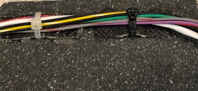
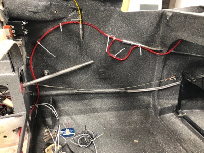
For attaching wires.
IMG_1566-2020-07-7-08-24.jpg

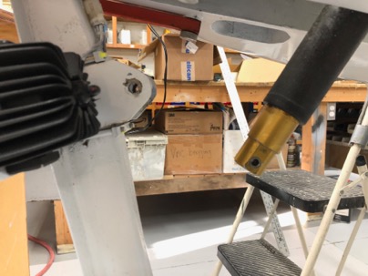
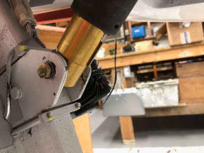
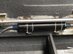
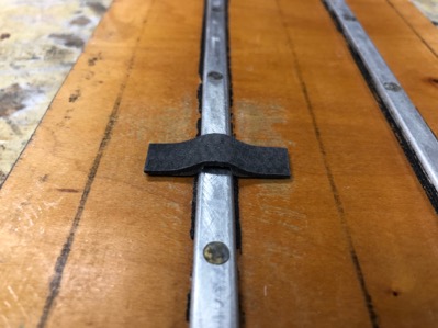
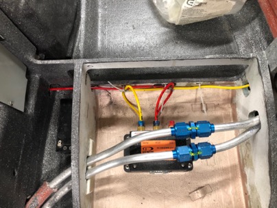
For attaching anything. Zip loops (5/8” wide) to secure my fuel filter.
IMG_1569-2020-07-7-08-24.jpg

You can also bond them directly to aluminum (such as holding wires to your engine) using a high temp JB weld epoxy.
IMG_1567-2020-07-7-08-24.jpg

ZL’s are very light weight and extremely strong. I built test rigs and have tested them to over 75 lbs of pull (tensile strength) before failure.
IMG_1240-2020-07-7-08-24.jpg

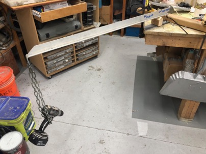
In testing has proven that NO zip tie (or even doubling up the strongest zip tie I have) is as strong as the ZL.
IMG_1232-2020-07-7-08-24.jpg

To test the ultimate pull strength I had to use nylon rope.
IMG_1237-2020-07-7-08-24.jpg

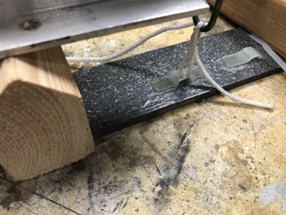
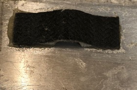
I discovered the ZL will always tear through the loop before separating from the base IF you bond them directly to sanded fiberglass.
IMG_1236-2020-07-7-08-24.jpg

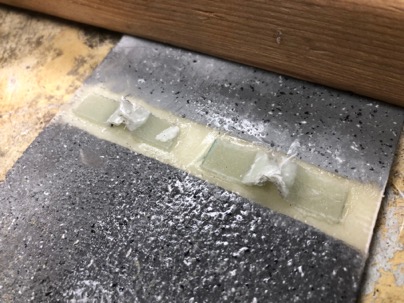
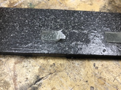
If you bond them to a painted surface the attachment strength of the ZL will only be as strong as the surface material strength. This shows how the ZL pulled the clear coat off the base coat.
IMG_1239-2020-07-7-08-24.jpg

It is always recommended that you plan for your general wire or tubing runs and glue the zip loops in the appropriate locations so they are bonded directly to the fiberglass structure prior to painting the interior of the plane. Wherever possible, I always lightly sand the surface of the plane prior gluing the ZL..

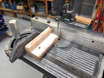
The jig to make the ZL is easy to make. My gig is made from scrap wood with two strips of 1/4” x 1/8” Al rails screwed to the surface.
IMG_1500-2020-07-7-08-24.jpg

Untitled_Artwork-2020-07-7-08-24.jpeg

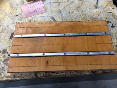
Guide lines on each side of the rail so I know how far I need to place the glass when doing the layups.
IMG_15022-2020-07-7-08-24.jpg

Procedure for making the ZL.
1. Wax the gig a few times
2. Use a small amount of flox to fillet each side of the AL rail to allow the glass to lay smoothly lay over the rails.
3. Apply 3 layers of BID or 2 layers of carbon over the rails You can make them ZL from scrap glass and extra epoxy you have from a layup. Use your excess glass/epoxy from a layup to make a few or as many ZL’s as you have material for. You can use West or a structural epoxy. Either works fine.
4. Apply peel ply to the surface.
5. Let cure. NOTE* I like to place my gig in a bag and pull a vacuum on the layup to remove excess epoxy.

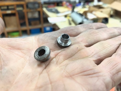
After cure, remove the layups from the jig, remove the peel ply and sand the flat back side to roughen the surface and remove the wax. Its easier to do it now, than to sand the individual ZL’s.
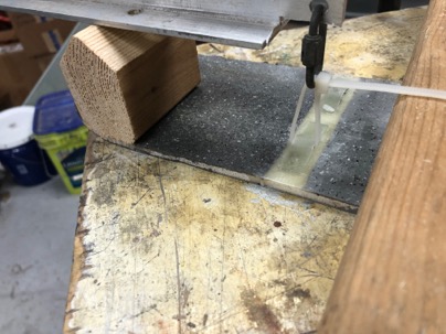
ON BANDSAW

  1. On the back use a pencil to mark a line 1/2” on each side of trough, and saw off the excess glass with the band saw. I use a hack saw blade (its 1/2” wide) as a straight edge guide for marking the cut line. You should now have a strip about 1 1/4” wide and the length of your gig.
  2. Make a simple guide gig to hold the strips 90 deg when cutting the individual ZL.

IMG_1503-2020-07-7-08-24.jpg

Cut the ZL to the desired length (using the fence of the bandsaw).

Generally I like to cut my ZL’s about 1/2” wide. I also make them from 1/4” (for just a few wires), to 5/8” wide if I have something heaver that I want to mount such as heavy cables, or a filter.
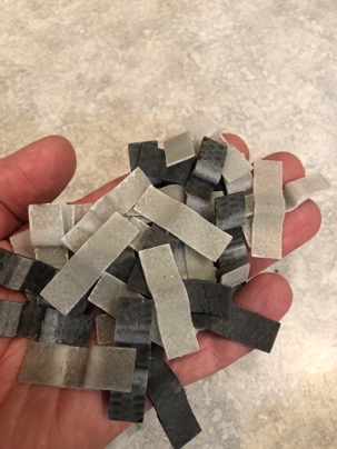
 IMG_1568-2020-07-7-08-24.jpg

Jul 04 2020

Panel ready for installation

Today was spent preparing the plane structure for accepting the instrument panel.

The panel was temporarily installed and all the switches and equipment was installed to make sure the clearances were ok in the old instrument panel.

I really like the way the panel came out and look forward to flying with it.

IMG_1538-2020-07-4-10-35.jpg

IMG_1541-2020-07-4-10-35.jpg

I forgot to add the passenger warning, so I called the vinyl print shop and they printed this out for me the same day. Using vinyl lettering really speeds up the process of fabricating the panel.

The lettering came out really nice and was really easy to do.

IMG_1549-2020-07-4-10-35.jpg

Jun 30 2020

Applying the vinyl Lettering to the panel

Here is a little trick when applying the lettering.

The decals are printing on a matt white base vinyl with black (or any color printing). Most print shops will accept a .pdf file of your lettering that you designed.

http://nickugolini.com/blog/wp-content/uploads/2020/07/ugolini-2020-06-30-11-33-1.pdf

After cutting out your graphic, be sure to use a black magic marker to color the edges of the white vinyl base layer. This will prevent you from seeing the white edge of the base layer..

IMG_1506-2020-06-30-11-33.jpg

This is a close up of the lettering on the panel. An easy way to place the decals is to position them in the right location. Use some masking tape on one side to make a flexible hinge. Fold the decal back to remove the backing and carefully fold the decal back over to apply. The hinge will keep the decal aligned for an exact placement.

IMG_15202-2020-06-30-11-33.jpg

IMG_15052-2020-06-30-11-33-1.jpg

This is how the panel will look after the lettering is installed. After the decals are applied, the next step is clear coating the panel to seal everything permanently in place.

For clear coating, you want to use any automotive clear coat, but I like a matt finish. You can use a glossy clear coat and add a flattener (from your paint supplier) to give you the matt finish. In my case I used a clear coat with the flattener already added to it.

IMG_1480-2020-06-30-11-33.jpg

Jun 29 2020

Painting the instrument panel

This is BIG day for me!! The painting of the instiurment panel.

First it was sanded with 220 grit paper to roughen the surface.

IMG_1496-2020-06-29-10-45.jpg

Next is a good cleaning with Bonderite to prepare it for the epoxy base coat

IMG_1497-2020-06-29-10-45.jpg

IMG_1498-2020-06-29-10-45.jpg

The Bonderite cleaner is essential to etch and clean the Aluminum prior to painting.

IMG_1499-2020-06-29-10-45.jpg
The flat black panel is done…

Jun 26 2020

Installing the radio cans

Installing the radio cans is simple and straight forward, but it does require a little thought into what kind of presentation you would like to display.

Typically, radios are installed with the fascia of the radio on the surface of the panel. Trying to just drill holes in a side plate is harder than one might think because of alignment of each side, trying to be perpendicular to the face of the panel, and where the mounting holes are in the cans (the are all different).. I find this method unacceptable because additionally, each radio or piece of equipment has a different depth of its face which (to me) unintentionally makes the panel look a bit disorganized with each piece of equipment just sticking out into the cabin a different amount.

I prefer to recess the cans into the panel to provide the exact amount of exposure necessary so all radios and equipment have the same exposure height for a nice organized look.

Actually, I found a very easy and fast technique for installing the cans which also ensures all the cans are perfectly perpendicular to the face of the panel. Once you decide on the amount of radio exposure desired, use this method to mount the radio cans. This is post from April 2016 when I used the same method for mounting the cans in my LongEZ. http://nickugolini.com/blog/?s=panel+mounting

Personally, I prefer using rivets instead of screws to attaching the cans to the side brackets which prevents any movement of the cans

Radios in place to check for the look I want.

IMG_1476-2020-06-26-11-55.jpg

Normally the Garmin has a .850” exposure. The Audio panel had a .780” exposure which would be a .070” mismatch. The Dynon sub panels have a .150” exposure. Here you can see how far I have recessed the radios into the dash everything lines up perfectly. After installation, all the exposures were within .020” of each other.

IMG_1477-2020-06-26-11-55.jpg

Dec 24 2019

Installing the nose lift

I decided to remove the Wright nose lift and replace it with a new Wilhelmson EZNose lift. I find the EZNoselift to be more repairable, smaller, lighter with better features (automatic extension).

IMG_08683-2019-12-24-20-25.jpg

The only major issue with the installation is the Wright nose lift uses a -5 bolt and the EZnoselift uses a -4 bolt.

The easy solution was to machine a couple of reducer bushing.

IMG_07152-2019-12-24-20-25.jpg

IMG_07162-2019-12-24-20-25.jpg

Done…

IMG_0718-2019-12-24-20-25.jpg