Category: Fuel System

Dec 23 2019

Air flow inlet

When I received the rebuilt Bendix throttle bottle from Airflow Performance (AFP) I also order an air filter and the flow guide to attach the filter to the fuel servo.

he strange thing is the flow guide has a 3.25” flange and the K&N filter they sell requires a 3.5” flange. I ask AFP what I should do and they really didn’t have an answer for the issue. I was told to just cut a piece of PVC pipe and use the ring as a spacer to fill the gap… Yikes! do people real do that sort of thing on their planes?

Amazingly, I happened to have some 1” AL stock of the right size and decided to machine my own flow guide.

IMG_0710-2019-12-23-20-09.jpg

That 1” AL is really thick and difficult to work with. After cutting the block off I needed to remove the center to make a hole.

IMG_0711-2019-12-23-20-09.jpg

IMG_0712-2019-12-23-20-09.jpg

Next is is spending a bit of fun time on the lathe.

IMG_0713-2019-12-23-20-09.jpg

Four hours later, I had a new flange with the 3.5” flange I wanted which was basically free. Now I’ll return the $135 air inlet back to AFP.

IMG_0714-2019-12-23-20-09.jpg

Dec 02 2019

Fuel Injection Installation

Today I started removing at the Ellison throttle body fuel system with the primer and facet pumps. I also sent the entire Bendix system to Airflow performance for overhaul.

IMG_0612-2019-12-2-20-07.jpg

Jan 19 2018

PMag Blast Tube

A requirement for a PMag installation is the addition of a blast tube on the base to assist in keeping the unit cool. Since PMag does not sell an adapter, it forced me grab some scissors and create a template. It took little time and is very light weight.

Here is two orientations I needed for both of my PMag.

IMG_9049-2018-01-19-16-21.jpg

Here is a very easy design to cut and bend the adaptor which insures the air is directed into the cooling grill on the bottom side of the unit.

IMG_9037-2018-01-19-16-21.jpg

After bending the metal (.015” AL) a tube was riveted on and all was sealed with a bit of RTV.

IMG_9048-2018-01-19-16-21.jpg

Enjoy.

http://nickugolini.com/blog/wp-content/uploads/2018/01/BlastTubeforPMag-1-19-18-2018-01-19-16-21.pdf

Jun 26 2014

Another AirFlow Performance Fuel Injecton emergency

Well, today I experienced my 3 inflight emergency in the last ONE year due to the same issue, a clogged AirFlow Performance finger filter (located on the fuel servo inlet).  The strange thing is I flew for thousands of hours with no fuel problems at all and now with in the last year I have had 3 fuel related emergencies.   In all cases, immediately after taking off the engine would not develop full power.  The engine started to backfire and sputter which necessitated an emergency go-around and landing.  The second time it happened, the tower had to divert an airliner which  resulted in a lengthy conversation with an FAA investigator.  (see http://nickugolini.com/blog/?s=airflow)

Fortunately I had only flown from my airport (JZI) to Mt Pleasant Airport (LRO) which was just a short 10 minute flight. The plane flew fine on the way over and developed the problem with no warning at all. Luckily, one of the flight instructors flew me back to my airport to get my tools and a spare finger filter to fix the the bird and after a short 30 min installation life is good again.

Once again as before, I had a problem with this FINGER FILTER. which is a major single point of failure on most canard AFP installations.

 wpid-IMG_4773-2014-06-26-16-49.jpeg

Basically, AFP/bendix has 3 filters inline to protect itself.   The filter supplied with their fuel pump is 125 micron (protects the pump).  The fuel servo finger filter is 75 micron has  about ONE square inch of filter area.  This is pathetic.  There is a third one in the spider which again is 75 microns with about 3/4″ sq inch of filter area.

IF you get a load of crap in your fuel (for me….    ?? the first time, rust the second time, now fine dust) your plane goes down.      All the fine stuff just flows through your fuel pump filter (125 micron) and accumulates in the finger filter 75 micron) or possibly in the spider filter until they totally clog up.  Honestly, It takes next to nothing to clog these tiny filters.

After talking to Kevin at  AFP (and Klaus) about the issue I found out there is an alternate way of plumbing the fuel system which will eliminate this single point of failure.  Just install a finer micron filter PRIOR to the finger filter on each tank outlet so it clogs first to protect the finger filter, duh…   This is NOT how we plumb our planes, nor is it discussed in the AFP manual.  Kevin told me this alternate fuel filter installation is very routine for RV airplanes and makes sense for ours too.   AFP even sells their fuel pump system without the 125 micron filter on it for the RV group.

Summit Racing sells a 63 microns filter with AN fittings with a HUGE amount of filter area (the filter is 12″ long).  Allstar Performance filter #40218, $61.    The reason for such a massive filter area is that being installed on the suction side of the fuel pump you want a large surface area so you do not reduce suction pressure to ensure the fuel doesn’t vaporized prior to the pump. There is no way this large filter (approx 20 sq inches of filter area) could restrict inlet pressure unless it was massively plugged.  If one does plug one up due to crap, (instantly recognizable due to low fuel flow) you switch tanks and use the other filter.   You protect the finger filter, the engine produces power, you keep flying, the FAA is happy.

Here is a couple key point if your building, planning, or flying a AFP or Bendex system.  

1. Consider the problems of this single point fuel failure and what can be done to prevent them or eliminate them.  Happened to me 3 times in a year, it could happen to you too.

2.  When taking off, be sure to include fuel flow in your scan.   The fuel pressure will be normal, but the fuel flow will decrease from about 12 gph on take off to 6-7 gph at full power setting.  If a fuel flow reduction occurs, retard the throttle which reduces air into the engine and about 2000 rpm the air/fuel mixture will be correct, and engine will smooth out and you can safely make it home.  Dont panic.

3.  I plan to carry my spare AFP finger filter with me in the plane at all times in case I get another load of crap in the fuel.  The finger filter is $75.  Cheap insurance.   If this happened on my recent 2800 mile trip to Burralls flyin, there would have been a much different outcome.

4.  Every annual, I’ll remove the finger filter and have it professionally cleaned.  BTW, you can buy a ultrasonic cleaner at Harbor Crap…use soap and water and blow it out.

For the cozy 3 I am building as well as another builder know (cozy 4) we are plumbing both fuel systems with 2 inline 63 micron filters immediately after the fuel tank outlets.

Fuel tank–>stop valve –>63 micron filter–>|selector valve –>electric fuel pump–>mechanical fuel pump–>75 micron finger filter–>fuel servo
Fuel tank–>stop valve –>63 micron filter–>|

The stop valves allow you to secure the fuel from each tank for servicing the filters.  Klaus recommends just fly them until the point one side plugs up and only then, remove and clean the filter.  

One would think having fuel injection solves all your problems…. no carburetor icing, great mixture control, the best fuel system you can put on your bird.  Life is great.    The one big issues is a fuel injection is very unforgiving about is dirty fuel which has lesser affect on a carburetor.   Hopefully, this post will make you think about your installation and possible issues of the plans type fuel system installation.

Nov 06 2012

Trip to Airflow Performance

Todays objective is to take my fuel injection system to Spartanburg, SC (about 200 miles away) to have they equipment tested. I think there is something wrong with it and some sort of fuel restriction caused my fuel emergency landing on Friday.

The trip started with a trip to do my civic duty…. Vote. I vote at the entrance to my subdivision which make the process quick (normally). Arriving at 6:45 I thought the line would be short, but alas it was quite long with a bit of rain.

wpid-IMG_3735-2012-11-6-18-14.jpg

Part of the reason for the long line was they only had 4 freaking voting machines in the building! It took an hour for the voting process, and I left Charleston at 7:45 for the 200 mile drive.

wpid-IMG_0104-2012-11-6-18-14.jpg

I arrived at Airflow Performance about 11 am for my meeting with Kyle.

wpid-CIMG1617-2012-11-6-18-14.jpg

The guys at Performance are terrific. Kyle loves to talk to customers and let them observe the testing process and explain what is going on with the tests and the results. Instant feedback on the problem and an opportunity to learn about my equipment. I LIKE it!

wpid-CIMG1619-2012-11-6-18-14.jpg

The shop always takes lots of pictures (before/after) of the equipment to ensure there is no question on the material condition of the items.

wpid-CIMG1620-2012-11-6-18-14.jpg

Here is the fuel servo mounted in the air flow box to test fuel output at different power levels.

wpid-CIMG1621-2012-11-6-18-14.jpg

Hum, the fuel servo passed all it’s tests perfectly, but the little fuel divider “the spider” failed.

When Kyle took the flow divider apart, he found the filter to be clogged and needed to be rebuilt. The little filter in the divider is what is restricting the fuel to the engine not allowing fuel flow at the normal max fuel flow of 12-13 gph . Currently, I could only get about 8 gph and can not get the rpm above 2480 rpm. During my flight on friday, I could only get 7 gph which is why I had to land in a hurry. NO fuel, NO power!

wpid-CIMG1622-2012-11-6-18-14.jpg

After talking with Kyle about my options and finding out that the normal service life of the unit is 10 years before overhaul (mine is 8 years old) the decision was made to just do a complete overhaul/rebuild of the equipment. It would have been due in another 2 years anyway. An overhaul is the most prudent and safest coarse of action.

I left Airflow at 12:30 pm, drove about 25 miles to Greenville for lunch at my favorite restaurant in SC. The Pita House. They make the best Mediterranean food in SC.

wpid-IMG_3736-2012-11-6-18-14.jpg

Mediterranean plate with gyro. It was SO good I order the same dinner to go. I’ll make some humus and have it dinner tonight!

wpid-IMG_3737-2012-11-6-18-14.jpg

After another 200 mile drive home, I passed my voting place at 4:30 pm and there NO freaking line at all. None! It would have taken me 5 minutes to vote. Next time I will wait until later in the day to vote when everyone is at work.

I won’t get my fuel servo and divider back until late next week, so I can now work on the house instead of spending my days at the airport. Yahoo!

Oct 27 2012

Fuel Readout Frustrations

Today was a frustrating evening of my own making. Friday, UPS delivered my updated PMag (electronic ignition system) and a very interesting electronic readout from Aircraft Extras which will be used for my fuel probe system.

The PMag’s were tested and upgraded and they found there was NO problem with their operation, so they were not a factor in the vibration issue.

The Aircraft Extras electronic programable display is very cool. It is a tiny display (1”x1”)with the ability to monitor 6 inputs. It be using it to monitor Left and Right fuel level, the main and standby batteries, voltage output of the MAP ( the manifold pressure sensor) which according to Klaus is the best way to monitor power output when used for drag reduction testing and one left over for a spare which I’ll eventually hook up to something to be decided later..? I think after I finish with drag reduction, I’ll connect #5 and #6 inputs to the fuel probes too. This way one can not only get fuel display (my primary use), but I can also use #5,6 to display a RED flashing screen to display LOW FUEL. If that doesn’t get my attention, nothing will! This little display and monitor anything with a voltage output and has LOTS of different display screens to chose from. I may use it to monitor belly board position, oil pressure or ??

wpid-FuelGauge-300-2012-10-27-20-58.jpg wpid-PastedGraphic-2012-10-27-20-582.tiff

A very small system. I only wish it could monitor more inputs (like 16 or 24) instead of just 6. It could be used to monitor anything electrical in the plane. Very cool little device.

wpid-PastedGraphic3-2012-10-27-20-582.tiff wpid-PastedGraphic2-2012-10-27-20-582.tiff wpid-PastedGraphic1-2012-10-27-20-582.tiff

Naturally, after receiving the AG6, I wanted to test it at home, get comfortable with the programing and operation before installing it in the plane. Ended staying up past midnight last night messing with the display to set it up for my needs. The AG6 VERY easy to configure and program once you get past how the software programing functions.

wpid-CIMG1567-2012-10-27-20-58.jpg

Low and behold I couldn’t get it to work quite like it should. I could tell it was alarming and functioning but there was no backlight color when it was alarmed. A red flashing display is very important to me for the intended use in the plane. The Princeton electronics in the test cell fuel calibrated and worked perfectly but not the readout.

wpid-CIMG1570-2012-10-27-20-58.jpg

This morning it was up early for more testing, more calls to the designer and finally sending him the data settings for evaluation.

Overall it is my goal is to develop a small, complete package of a fuel probe and a readout system for those canard flyers who don’t, won’t, or can’t upgrade their planes to latest Glass Panel type displays. Something that can be easily installed in any canard even if one has very limited panel space (like my plane).

Overall, this is no different from developmental pains of designing the probes. It took almost a year of going back and forth with Princeton Electronics to get the level sensing electronics module working properly. I really like the small foot print of the readout and can’t wait to get it calibrated and working in the plane. It is just a matter of figuring out what is wrong with my setup. After the proper configuration for the fuel level alarms (1/4 tank, 1/8 tank) is determined, the designer will configured and saved the program file so when a canard owner buys one of his readouts for my probes, it will be pre-programed to my specifications so it can be used right out of the box with no fiddling.

After a morning of frustration, it was off to the airport to modify the instrument panel for the readout, wiring and mounting of the electronics which will ultimately occur when the display is working properly. I want to do as much tomorrow as I can as on Tuesday (after install my hydraulic lifters delivery on monday) as it is going to be COLD here (high in the 50’s) which is the result of the Hurricane Sandy which is moving through the area today.

NOTE: After returning the display and getting a new one, I found out that the original display was working perfectly and it was my fault the backlighting (alarms) were not working…. I DIDNT hook up a small jumper wire which powers the light of the display. No backlight power, no colored alarms! Sometimes I am amazed at my ability to frustrate myself.

After reviewing the installation instructions I found my mistake, hooked up the jumper and all the backlight functions of the display worked as designed. The good part of the story is I found the designer was very helpful at trying to solve my self induced problem, and I learned a lot about how to use and program the display.

Watched 3 episodes of a new show on CW called “Arrow”. It is taken from the comics and is about a man who is fighting crime in the city with a bow and Arrow. Sort of like batman with a bow. Actually, it is nicely done.

Oct 16 2010

Fuel Servo Inlet Duct

The last few days were spent working on the fuel servo inlet duct.  I wanted to use the armpit scoop on the right side of the cowl instead of cutting through the firewall into the hell hole.

After visualizing what was needed the part had to be carved out of foam.  First I had to carve the part out of foam and glassed. 

After a few hour under a vacuum, the part was read to be revealed.

Here it is with the foam still on the inside. 

Tony stopped by again to check out the work.  He thought it all looked “smashing” and “very clean”. 

Here is the duct system in the final form.  Some paint and it will look great.

Sep 10 2010

Panel troubles and more

The last few days have been total devoted to getting the panel ready for lettering as I thought the effort would be short and easy.    While looking at the panel I decided I didn’t like the big chrome bezels of the LED lights.  I floxed the holes shut and redrilled them to accommodate simple LED holders.  I dont like the knobs either, so I am going to machine some that I like.  It is easy to do on a lathe.  I also cut the shaft of the potentiometer control shaft off so I can reduce the exposure of the knobs. 

The before look

The after look.

I decided it was best to fully assemble everything to make sure there were no surprises.  The nutplates for the panel were floxed in and I like the stiffness of the panel when placed in it’s frame and secured.

Note the gold box in the above picture (the autopilot elevator servo. 

When looking from the other side I noticed it was going to hit the com panel and transponder radio cans.  FU****K!!  The servo has to go.

You can see the carbon box just forward of the servo into which the radio can is secured.  Bye bye, servo….

Not only did the servo hit but when I changed out from a Garmin 327 to a Garmin 330 transponder, I found the transponder’s can was 2.5″ longer than what I had planed for which made the can hit the elevator control rod.   SH*T! 

Major redesign time!  Hum, IF I switch the places of the com and transponder then the com panel (with the shorter can) will allow me to gain the clearance I need for the control stick.    After a few hours work…done.  Clearance is good now.

Since the panel is taking longer than I anticipated to finish off,  I took a few hours to to get some critical measurement from the engine I needed to send to Airflow Performance so I could get the fuel lines made.  AFP currently has the fuel servo for a minor change, and they were waiting for me to call them with the injector line lengths so they could build them and ship all the stuff back to me.    I finished making the cylinder cooling plates (an improved design to the down draft system) and took some heavy wire to simulate the fuel lines and route everything to make template lines. 

After a while of bending, cutting, rebending, etc I was satisfied with the routing and placed my order for the lines.  They should be here by next Wed.  I’ll then be able to fully assemble the engine! 

I found a new home to re-install the autopilot servo.  Here, I am using the fiberglass spring template to make a new control arm for the elevator torque tube.  I’ll attach the servo to this tab.  It will act as a carbon control arm for the servo.

Apr 19 2010

Cylinders 2 and 4 installed

Today was a long day of work on the plane.   It is hard to believe I have been working on the plane for a year and have put in 940 hrs on the project.    The number of hours is not surprising given the plane was completely stripped of everything except the basic structure and an extreme amount of customization and design work done.   I am determined to put out maximum effort for the next few months to get the project completed.  Besides, I really want to fly the bird!

Tony stopped by to learn the finer details of installing engine cylinders. 

Job well done!  Doesnt he look happy.

Cylinders 2/4 are installed.  I really like how the red crackle powder coating came out on the valve covers.

I needed to make a new bracket and bushings for the electronic ignition coils.

Simulated fuel injection lines were routed to determine the exact length needed.  They will manufactured by Airflow Performance after I get the fuel servo back from Calif to check on the fuel outlet position before I commit to the finial lengths.  I don’t want to be surprised when I put on the sump. 

This is the stbd side

The port side. 

Apr 06 2010

Fuel probes are installed!

Today,  I reached a few personal milestones by shipping off the instrument panel and installing two capacitance fuel probes of my design.      There is a a bit more to this story so get ready for a long read. 

First
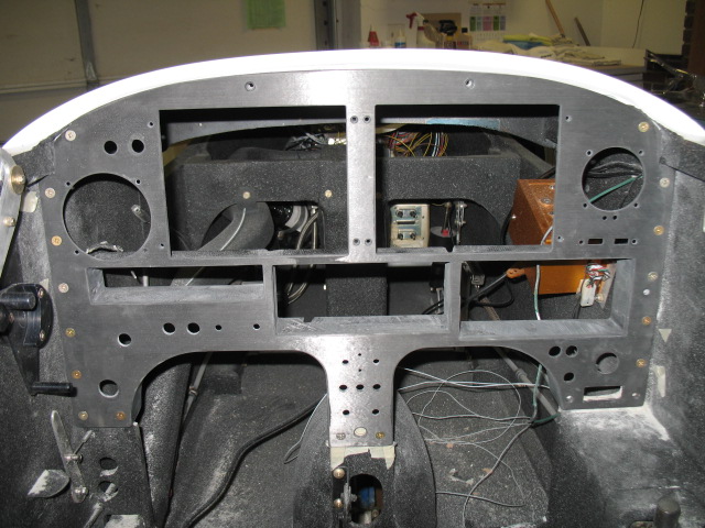
I completed everything left to do on the instrument panel, wrote the testing and modification procedure for Pat, then shipped it to LA by FedEx 3 day.  P1 Prototypes (Pats composite fabrication company) has some shop time available (by his top technician) and he will personally build and attach radio brackets, leg opening flanges and clear coat the panel to my specifications.   It will come back ready to install.  How cool is that?

Second,
For years, while visiting airshows, I always checked out vendors looking and comparing various remote capacitance fuel probes (because I wanted some in my bird).   They were all very simple, small and reliable, and VERY EXPENSIVE ($150- 175 each) and I am too dam cheap to spend mucho dinero for a simple product which doesnt even include the electronics.   Ouch!   A few months ago I had an idea to make a probe setup specifically designed for a canard installation.   Finally, a fuel probe which would work in a non-Cozy canard.

Non-Cozy canards are built in way which does not lend itself to the installation of capacitance fuel probes (CFP) .    Cozy’s have a nice fairing forward of firewall which can be used to cover and hide the probe installation.   I have seen a few attempts to install probes in LongEZ’s, but have never liked the final look of the avaliable products.   Either they are puck type which is harder to seal, or they are WAY too tall to hide.    The only advantage to these systems is that they are removable after installation.    Mine are not, but what can go wrong with a tube and with a wire in it?

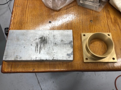
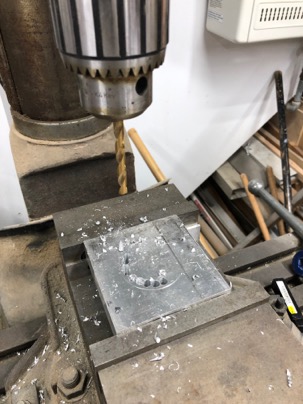
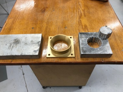
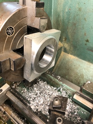
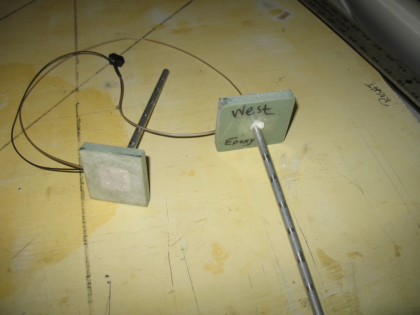
Initially the design started with a probe.   A proper installation requires a very short probe less than 3/8″ tall.   The shortest probe I have seen was at least 1.5″ tall (or a puck at 1″ tall).  This probe’s height is sized to fit into the space of the 10mm foam core of the strake.   After many designs a working prototype was finished.

Less than 3/8″ tall it can be easily and quickly installed.  Is is completely invisible after installation and fits nicely in the foam core space.

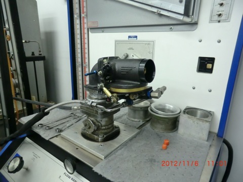
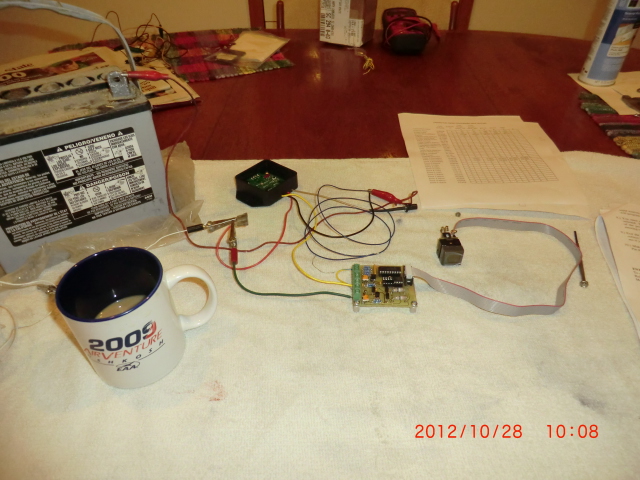
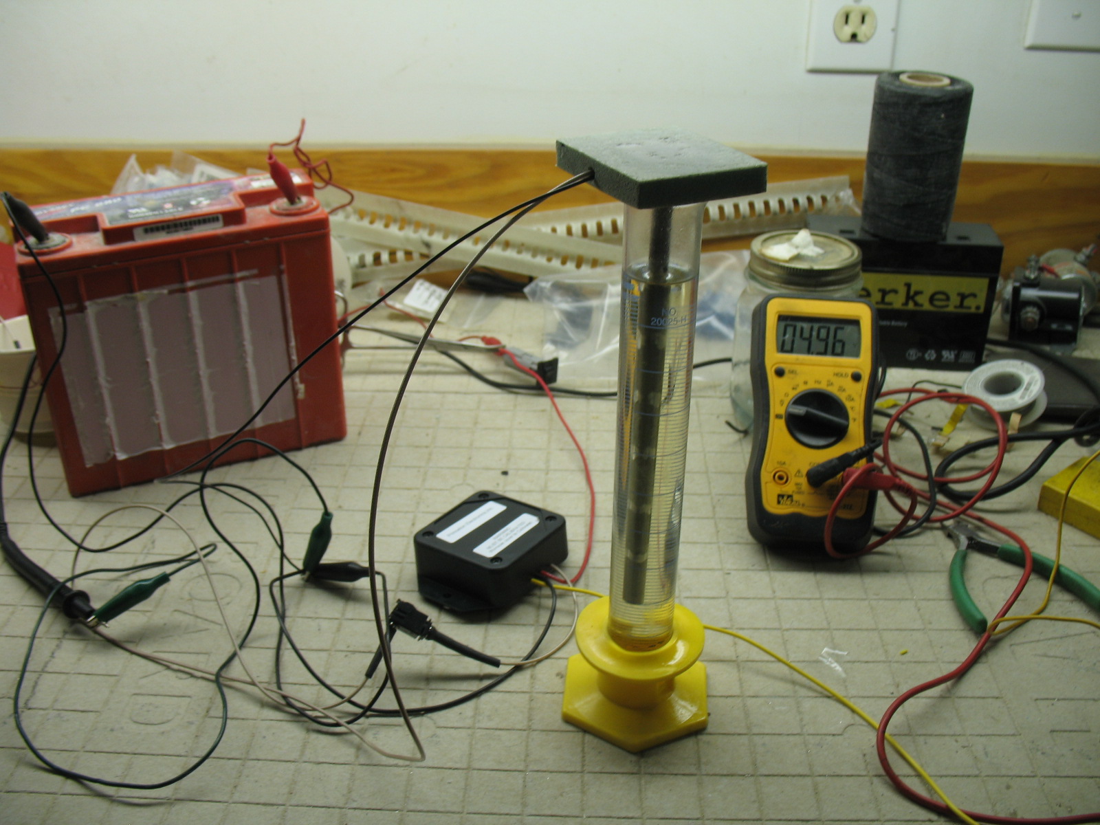
A test cell was built to check the height dimension,  the dielectric constant of  two epoxies and the accuracy of the voltage output for two common fuels I use,  MOGAS and AVGAS.

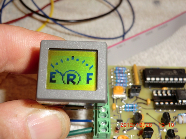
Next, some electronics are needed to make these probes work.

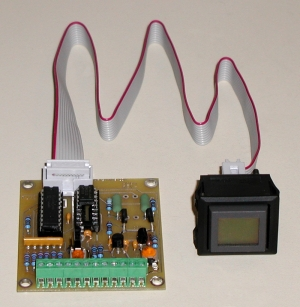
I knew Princeton Technology built capacitance electronic fuel probe modules.   They build puck styles and other various remote probe styles and has a great reputation.   At the SNF airshow last year,  I talked to  Todd Stehouwer (the owner of Princeton) and finally convinced him to let me help him.   I could easily see a wide open market for an EZ probe system.    As many canards owners rewire their canards to install improved electronic systems such as Grand Rapid, Dyson, ECI, the market was wide open for a new product line.   All that was needed is Todd’s help to develop an EZ specific electronics product so he could sell product to make mucho dinero   Why did I do this?   Because I freaken needed some for myself  and someday I might need his help.  “Pay it forward”!

After many months of emails, calls, a few miss steps, Todd finally completed the engineering for the module needed allow this probe to function.    He used the test cell I sent him (MGS with AVGAS) for setup, calibration and testing.    The nice thing about his electronics module is that it has FIVE calibrations point to fine tune the electronics to your fuel tank profile and can be used with either AVGAS or MOGAS (you have to recalibrate it for the dielectric of the fuel).   

Well, call me an over cautious engineer, but I always have to check everything out before I put my cra*k, oops, foot out there to get stepped on.    I want to be sure I would be as happy with this design as if someone else presented me with a similar design for evaluation.

Here is a couple of issues of concern to me.

1.  Will fuel resistance of either WEST or MGS  (two common epoxies) work for this application?  I know MGS is multi-fuel safe.  A quick call to WEST Tech Support confirmed  WEST resin is fuel safe for AVGAS or MOGAS (NO Ethanol) fuels.   My main concern was the possiblity builders might no have MGS available, but most of us have WEST handy (or can easily go to a local boating store to buy a pint).  Epoxy/fuel check …good.

2.  Next does the epoxy affect the overall capacitance of the system?   Epoxy is a dielectric.  Is the dielectric (hence functionality) a factor and/or epoxy dependent?  I built two test cell to evaluate.  One using WEST and one using MGS epoxy. 

After testing by Jack Wilhelmson and myself,  we found the epoxy made no difference to a calibrated probe in AVGAS or MOGAS.  Epoxy/Capacitance  check …good.

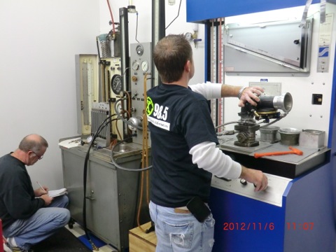
3.  Does the OVERALL system work reliably?  A test rig was set up and after gathering about 40 data points, I found overall the system works very well.  Voltage output for different heights were exactly repeatable about 85% of the time.  Sometime, it would just be off just a small amount 0.1-0.2 V or so, but no surprises.  I dont even know if that small a voltage would make a difference on a display.   This could be partly due to the difficulty of measuring the capacitance on a 7.75″ probe (the height of the strake) or the accuracy of the VOM.    Todd and Jack also tested the electronics.    Accuracy check.  …good.

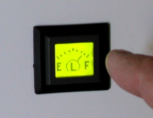
Here you see the probe sitting in MOGAS at “FULL”  tank  level in my home test rig.  The voltage shows is 4.96v.  

To calibrate the system, just fill your tank to your personal “empty” level …press “SET” to lock in “Empty” point.  Fill the tank to the 1/4 level (or fuel gals)… press “SET”.  Repeat for 1/2, 3/4 and FULL.    Took just a few moments. 

Before you read further be warned, in my opinion everything in life has Ying, Yang….. the Black and White,  Good and Bad sides.  Here is this probe’s good/bad side.

The BAD:
1.  This is a PERMANENT install.  Everything is glassed into place.  You’ll never get it out.  Be smart and careful with the installation.
2.  If it stops working, you’ll have to abandon the exiting probe and install one in a new location.  

The GOOD:
1.  It is the only probe/electronic system specifically designed and built for a canard aircraft (Varieze’s to Cozy 4)
2.  The electronics are easily removable/serviceable (there is a quick disconnect on the fuel probe wire).
3.  It is VERY easy to install in a few hours.  Installing two probes took me around 2 hrs and I didnt know what the heck I was doing!

The UNKNOWN:
I have done my best to ensure this solution will work.    I wanted to test everything and be as absolutely confident as possible before I spent the time installing it.   Before I recommend it with complete confidence,  I  still need to complete the wiring of the plane, calibrate the system with 100LL and gather many data points comparing the sight glasses and electronic output over an extended period of time .  

If you are a experimenter like me who likes to try new things (testing indicates this system will work) then go for your own installation.  If you are a timid soul, then I would recommend waiting until I start flying this bird and get some real life data before thinking of installing it.

The Installation:
Now the fun part.  The entire process took about 2 hrs start to finish.  

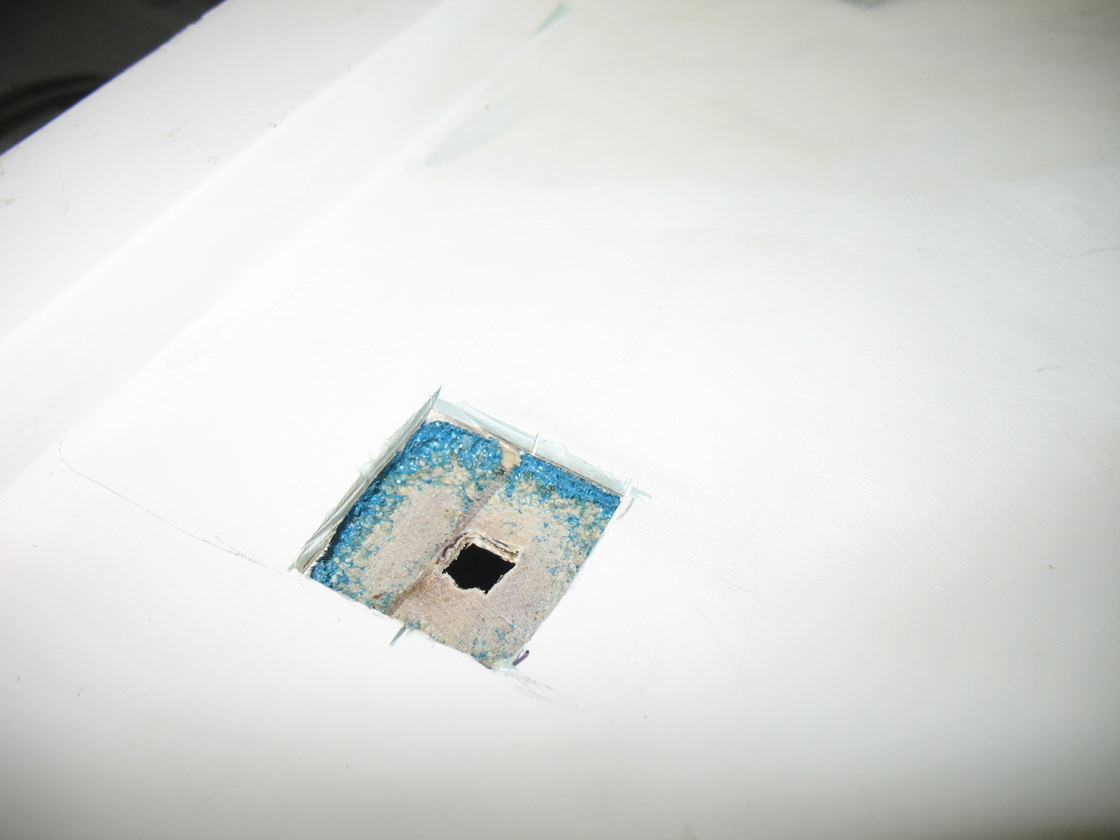
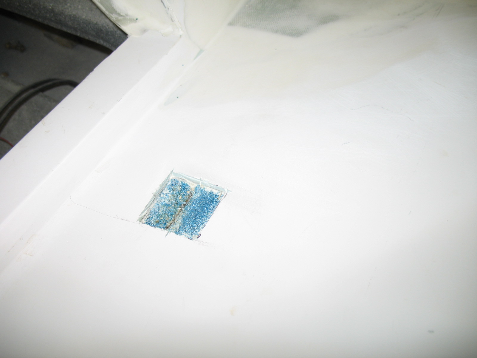
Measure and cut a hole in the outer skin of the plane.

Remove the foam to the inner skin.  Sand the inner skin.


Drill a 3/16″  hole  horizontal below the Longerons, into the foam below the upper skin.  Fish the wires though the hole. 

NOTE: 
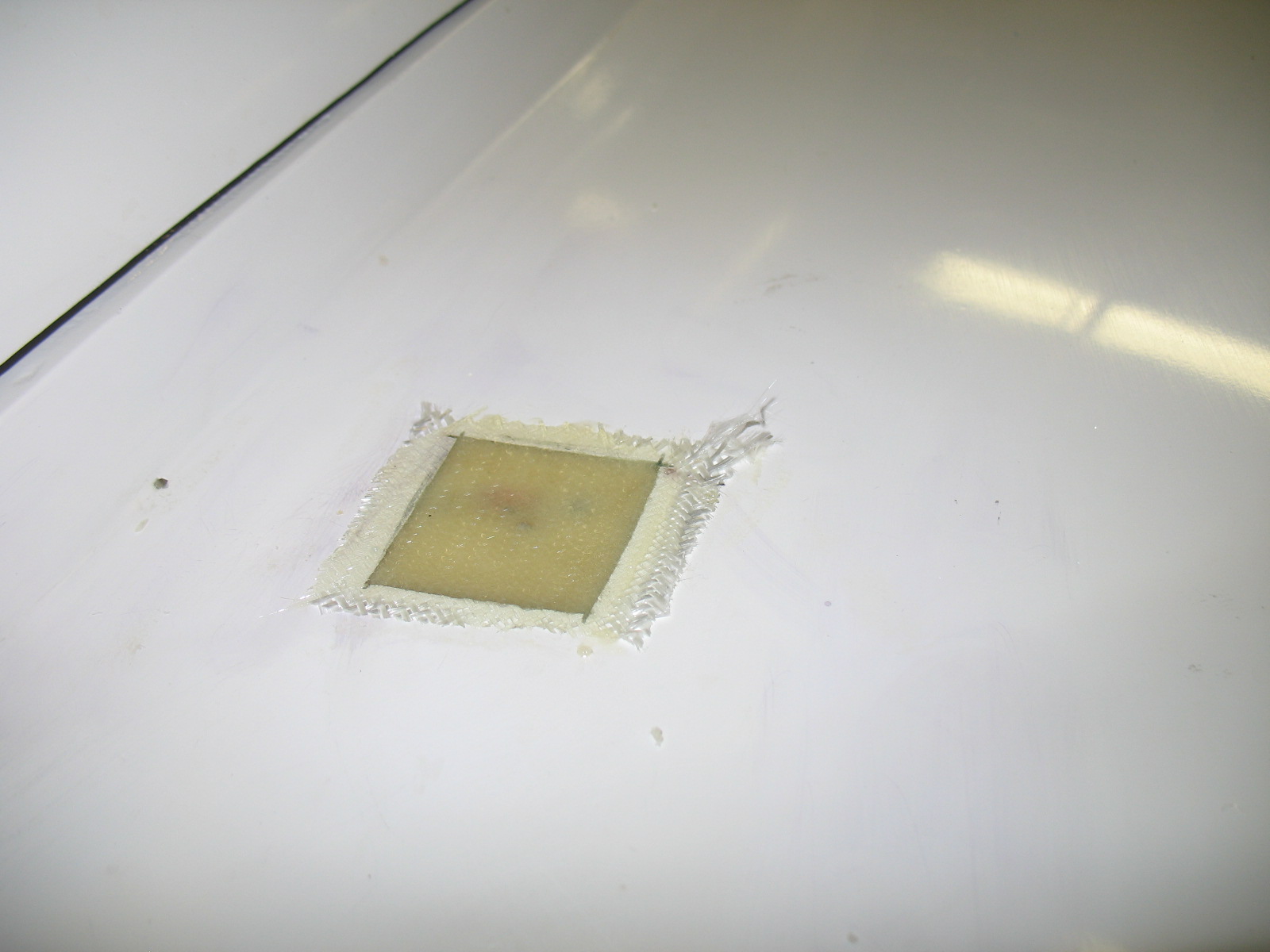
When I drilled the holes for the wires, I drilled from the cabin to the strake and was afraid I would drill into the tank.   Being careful, I angled the drill a bit too much and punched a small hole in the upper skin.  No big deal.  Better than drilling into the tank.   A little filler will make for an easily fix. 

Were I to do this again, I would drill from the hole into the cabin.   Just take some welding wire, flatten and sharpen the end into a flexible drill.  Insert your home made drill into the foam from the hole side and you can easily bore through the exterior and interior glass sides.  Using the pilot hole you can then follow it with a real drill from the cabin side….. NO CHANCE  of drilling into the fuel tank!!

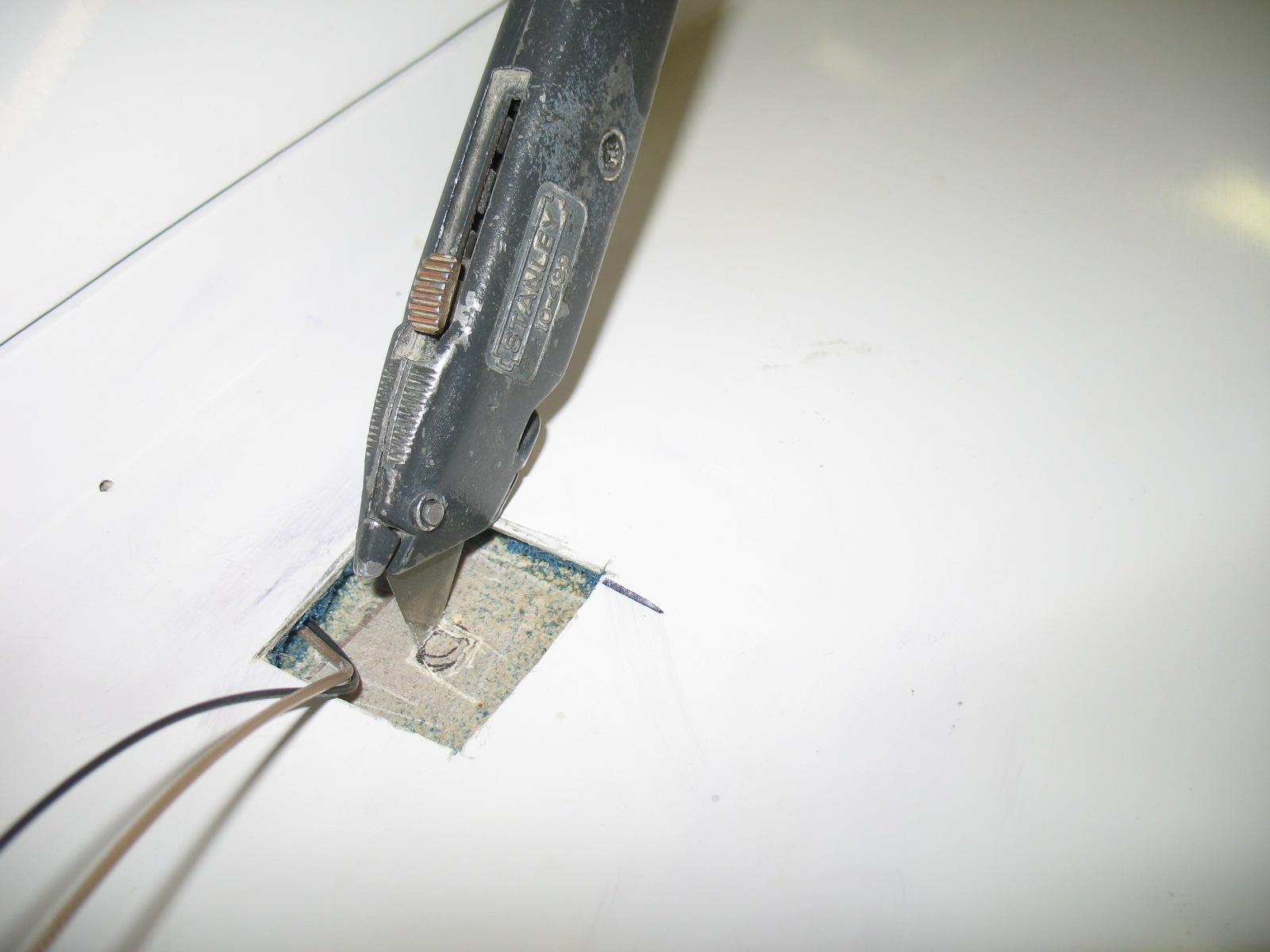
Lastly, use the razor knife to cut a square opening in the glass  inner skin of the strake for the probe tube.  The razor knife is used to prevent the possibility of  getting some chips into the tank which wound invariably happen if I had drilled a hole.   After you cut the 3 sides of the hole,  just bend the tab up and break it off….  no chips.

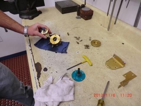
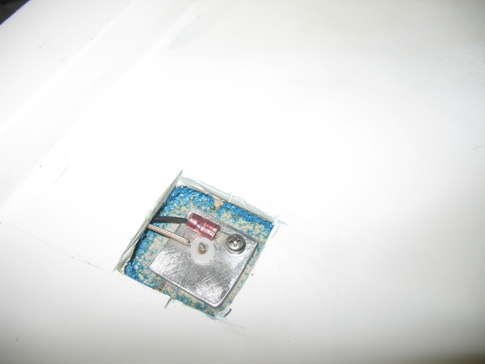
A nice hole, all sanded and ready for glassing.  Attach the wires to the probe.

Mix some wet flox, and butter the bottom of the probe, install it into the tank and then fill the entire cavity with even wetter flox.  The probe/wires are completely encapsulated (potted) into the tank with wet flox…. did I say it is permanent?   In my mind there is no possible chance of fuel leakage. 


After a bit of reflection, I could see a few variation to an installation….

IF you DID NOT wish to immediately repaint, just cover the area around the hole (to protect your paint), cut the hole and install as shown.  When cured, remove the protective tape/paper for an unblemished paint job.   Make a painted Alum cover (like wing bolt covers) and RTV it over the probe hole.    Save the painting till later.

IF you wish to immediately repaint the area,  first mark the opening, take a sander and feather the micro back 1/2″, THEN cut the hole.   When floxing the probe incorporate 1 layer of BID in to the repair.    After curing cover the area with micro and sand every thing flush.  I doubt you would even have to put a second coat of micro on it.  Then paint. 

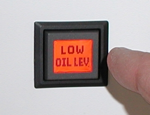
If  you are interested in purchasing the electronics call Grand Rapids Technology and ask for the Princeton CANARD capacitance electronics box.  Princeton is selling the CANARD module (with 5 calibration points) for $95 each .  

I am considering selling the probes for $40 each if anyone is interested.    You can easily make your own…  I did it.   I thought about detailing the construction of the probe, but decided against.  I know it is a few $$$, but I’ll be more confident they will work correctly for others if they are an exact copy of mine which has been tested.  By the time you buy the materials, have them shipped to you, machine the parts in a lathe, etc, it is not worth your time and expense.  I certainly wouldnt have gone though all this shit if I could have just bought a system off the shelf for a few bucks.

One afternoon while Todd and I were talking and trying to find a suitable name to order this specific electronics modification, Todd suggested calling them the “Nick Ugolini” electronics.  It is the name Todd jokingly gave them due to the frequently calls I made to get it working.     I thought it might be a bit to pretentious so I thought it best to decline…. 

Am I humble sort of guy or what?

What?