Jan 20 2010

Cylinder Baffling

Work continues on the down draft conversion.  I am making the lower part of the DD cooling system in aluminum and the curves and upper part will be glass.  I am starting to realize with the close tolerances and difficulty of working with Al, that in the future, I would probably just make the head support in Al, and all the rest in glass.  It will be interesting to see after I am done if the effort is worthe the result, and which method might be the best in the future.  I’ll be doing this all over again for my cozy 4.  I must say, it does make for a nice clean installation ….

#1 Cylinder  

#2 Cylinder 

This is the brand new lycoming flow ported, high compression cylinder from Ly-Con.  Beautiful!  Unfortunately, Ly-Con sent 0-360 cylinder NOT 0-320 cylinder.  I feel it was totally their mistake, but we compromised on the shipping….  F***   Always something isnt there!

Received the in instrument panel test panel from the fabricator.  Overall it was GREAT!  All the instruments fit as planned with just a few minor adjustment on the holes.  I cant wait to see it populated and fit into the plane.

I also made a blended winglet test model to test out a new construction method I developed.  I want to put blended winglets on the plane.  I figured out a very quick way to build them that is self jigging, self leveling and leaves no possiblity of error or misalignment.  A complete coversion should take about two weeks.   Stay tuned for further developments.

Jan 13 2010

Cooling Inlet Design

Today was spent working on the cooling system inlet design.  After making a few plugs I wasnt happy with, I turned to AutoCad to model it on paper before building.  It is so much easier when you can see exactly what you’ll end up with before you start.  I really do need to start learning 3D model.  It would make my life much easier.

Initially I started out with a few hot wire cut pieces.

Pat was happy with this design, but I was not.    I am not comfortable with a funky NACA scoop instead of the tried and true ram air inlet.   The current plan is to first make a ram air inlet, then add the ramps (so Pat is happy) and if things don’t work out, I’ll have a fall back position.  Chop off the ramps and I am back to ram air!

This is a pdf file of the cowl design/cooling system design I came up with.  It is as tight to the engine as I could make it (1/2″ clearences over the spark plugs and plentum box).   

cowl design  1

Tomorrow, I’ll glass the inlet tube I made, then start working on the ducts.  Much to do, much to learn.

Jan 11 2010

Change in Direction

I have changed direction a bit.  I was working toward updraft cooling with this plane.   I have decided to working on downdraft cooling.  It will keep me busy for a month or two….  oh well, what else would I be doing…maybe retire?

Today was spent cutting and cleaning up of the strakes and planning for the down draft conversion.

I also stopped by Tony’s house to check out his work on DD cooling.  Funny, a few months ago, I was trying to convince Tony to use DD cooling and gave him a bunch of ideas, now I am checking out his work for ideas.   He is a terrific builder so it was interesting to talk about his techniques and experiences. .

Jan 09 2010

A New Year

It is the beginning of a new year. 2010. How does one say that these days? Is it ” Two Thousand Ten” or is it  “Twenty Ten” ?

My pronouncement would be Twenty Ten, since the only reason we called the 20th decade as ” TWO THOUSAND AND ##” is because of the movie “2001, A Space Odyssey”. The naming of the movie influenced the entire next decade of yearly naming conventions.  Can you imagine calling 2004 a “twenty oh four”.   No, it is only because of this movie this decade was different.

Well, I am finally back to work on the plane. The last time I physically worked on the plane was on 27 Nov.  For the month of Dec, I worked exclusively on the wiring diagrams of the plane.  When I finished on 30 Dec, I had put in 132 hrs of drafting time.   That’s about 25 hr with the holidays.  I ended up with 35 pages of drawings and a half completed spreadsheet (it will be filled in as I wire the plane).

I decided to document the wiring in a similar way to my Toyota Truck Wiring Book is written. The drawings are broken down by systems like charging, starting, lights, com panel, etc.  

This way if there is a problem with something electrical, it will be very easy to trouble shoot JUST that system. A light doesn’t work, it will be easy to see at a glance the entire lighting system without trying to dig out the wires of interest amongst other unrelated wire on a schematic.  It is a MAJOR PITA to document everything this way and a little more difficult to wire but the effort was definitely worth it.

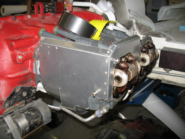
Now that the really hard part is done, the wiring plan, I can start back on finishing the things necessary to get me to the point of wiring. The engine is next. I want composite baffles on the plane instead of the aluminum type for more ridge baffles and better sealing of the cooling air. The currently installed baffles have massive air leaks around the perimeter.

Lots of red RTV is on the old baffles.

Composite baffles are more time consuming to make, but the advantages are perfect sealing of the engine, no cracking and you can do compound curved to attach the flexible baffles to. The extra effort creates is the best possible seal. We need the best possible cooling for the extra HP this engine is going to generate (estimated at 195 hp from a IO-320).  The baffles will look a little strange, as it will be comprised of both composite and fiberglass but it is best to match each material to it’s unique physical properties.

Here is the bottom engine baffles.   

They were re-imagined in composites.  The form is foam and the glass is lay-ed out in order of use.

The part is vacuumed down to the table after coating with epoxy. 

Carbon sure does look good when you are done and uncover your work.   I’ll uncover the rest of the part tomorrow after the epoxy has had a chance to get a little harder.