Jun
07
2011
Today the cowl was given a new oil door since the original one was glassed over and the forward lip flanges were added to the cowl.

I really the new ducts. The airflow is very direct and open to the cylinders. With blast air directly on #3 (my current hottest cylinder) I should see much better cooling.

Tomorrow, a few nutplates to install, put the baffling back on and the bird should be ready for testing. The cowl mod was started on Saturday and completed on Wed. The work went very quicky.
Jun
05
2011
Yesterday was extremely busy and super hot out. Today’s work is much easier since the only goal is to glass the cowl.
The back section of the cowl was dam-ed and pour foamed.


Carving is the fun part. You can get as creative as you want before you lock the shape out in fiberglass.


Some duct tape as a release and it is ready to be glassed.

The new shape is beginning to grow on me. The cowl is much more aerodynamic now. Let’s let the glass cure before the next step of cowl mods.

Jun
04
2011
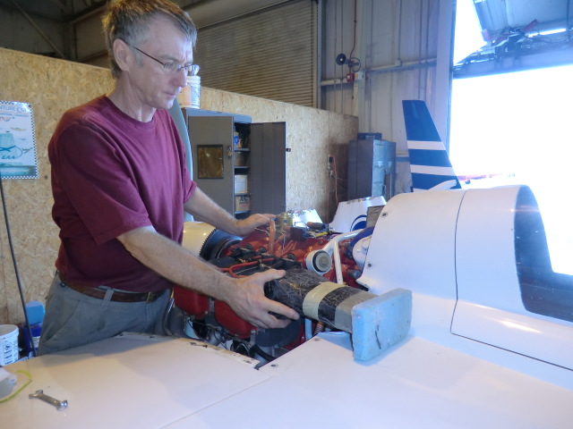
I went flying yesterday and while the cylinder temperatures did come down about 15-20f I am still not able to achieve full power. The decision was made to cut the inlets off and install a set of inlets I had made about a year ago but never installed. This is the original opening size. I had removed the shoulder from the cowl and fashioned it into an inlet duct of approximately 7.5 sq inches.

Stbd side.

Tony is holding the new duct into postion after removing the old inlet system.

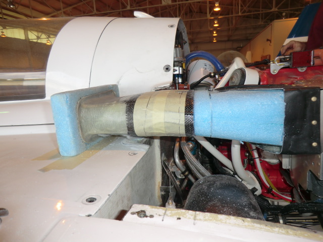
The shape of the new duct is rectangular in opening and MUCH straighter into to the plenum box. the inlet was fashioned using hot wire cut wing foam. The inlet area of these new ducts is slightly bigger than my plane at about 11.5-12 in sq.

Working the port side was a bit more difficult as I needed to save part of the duct which

the new nose has been fitted to the duct.

The cowl is cutaway and fitted for the new nose.

the nose section was dam-ed and pour foam was used to fix it in place.

May
02
2011
Today I am molding the lens for the wing lights. After a number of tests I found I could bang them out quite easily.
A couple of notes….
1. Cover the splash with some fabric. I found an old tee shirt taped to the splash to prevent wrinkles (which will show up in the lens) after cooling
2. Heat the oven to about 250F
3. heat the Plexiglas for about 15 minutes
4. when you removed the Plexiglas from the oven work quickly (as it cools VERY quickly) . Keep it covered with a warm towel to prevent cooling

Here is a bunch of them made as spares.

I tried heating the oven up to 350 f and the plexiglass started to bubble.

Now that the lens are made I outlined the shape I wanted for the opening and started cutting.

and cut out a cavity in the wing. You can see the flange on top of the wing will will slid into the opening and floxed in place.

This is how the the lights will look installed. You can see the lens mounting flange loosely planced in the light opening.

Very cool!
I need to make a webpage on this subject….. I have lots more details on each step… so many projects and sol little time.. Here is a few more picture for you.

After installation, I wanted to be sure the structure would not be impacted by heat generated by the light. The light was powered up and I left it on for about an hour to see if the surface of the wing was hot. The surface was barely warm in static air, so when using the lights in flight the wind will provide a lot of cooling. So I determined the operation of the lights resulted in no impact to the structure.

Update: I found the lenses would crack at the screw holes. I went though a couple of set of lenses, trying different way of attaching them with no joy. The last time I had my car windshield replaced I noticed they used an adhesive so I finally decided to just use adhesive to glue them in place (used clear RTV). Worked great.

Apr
30
2011
After the splash was made of the leading edge of the wings, a flange needed to be made to support the lens. I used 4 layers of bid.

After wetting out the BID, it was placed in the wing splashes to set up.

Here you can see the splashes (left) the flange parts (right) lights and the 3 way supports for the lights to allow them to be aimed (adjusted).

Apr
27
2011
I decided to try a second type of earth bucket. The first type of earth bucket was a pain to make. I felt if I just used gravel (river stone) as a storage medium would make the earth buckets much easier to fabricate, although it would not store as much water.

I tested river stone (small stone) or the larger decorative stone. Much to my surprise the decorative stone held a little more water. A little over 3/4 of a gal. Yah! The river stone can be purchased for about $3.50 per bag and the two bags will make 3 earth buckets.

To make the bucket, a center tube (3″ pvc) is cut about 8″ long. I put tape across the top to prevent the rock from filling the “wick” tube. I then filled the bucket with gravel to about 1″ below the wick. Drill some holes in the side of the bucket at the top of the gravel layer to allow excess water to drain out.
I found it easiest to install the fill tube after filling with gravel . After inserting the fill tube, I covered the gravel with some weed barrier cloth, cut open the center tube to allow the dirt to fill the wick tube and filled the bucket with water. I am not sure if you really need to cover the gravel or if you can just put soil directly on the rock. I am sure the soil would not migrate into the rock area very far. Put in your plant, and fill the storage area with water and you are done.

The plane is looking good! Soon I’ll be flying her.

Apr
26
2011
Bob stopped by to check out my work….

The cowl bump out is done. Ready to flox on and micro.

Jan
19
2011
I wanted to show you the greatest thing for wiring a composite plane I have ever come up with.
The big problem with wiring one of our birds is how do you secure the wires to the structure. You cant just put screws in the side of the plane. Securing wires is a big issue…
I came up with a great way to do this which weighs almost nothing. I call them zip tie loops (ZTL)s. After you fabricate them (which takes very little time) you can secure them anywhere on your structure by just gluing them in place with a little bit of flox. They are so light you dont even need to secure them or hold them in place while the floxis curing. Just wet the back side and postion. Once cured, they will self destruct before they will come loose.

Just stick them where ever you need to secure a wire bundle. I must have 30 or 40 of them in the plane now.
ZTL’s are made by taking 3 layers of wetted glass and laying them over a rod or some square material (1/4″ x 1/4″ I would recommend at least 1/4″ high. In this picture I just used some scrap 1/4″ delron rod I had handy. In this case I tired two different tests. Case one, 1 bid, 1 carbon BID (fair) and case 2, 2 BID and 1 carbon (better). I dont think the carbon helped much so I would just recommend 3 or 4 layers of BID.

I like to use the LoVac method to make sure there is a nice tight loop in the strip.

After curing I used my radial arm saw to cut the slots in the long strip and a pair of scissors to separate the loops. A little paint and they are ready to install in the plane.

Here is some ZTL’s that I am spraying black to match the interior of the plane.

Quick and EZ.
Nov
22
2010
Doug bought over some more dirt today. Four huge truck loads of fill soil to be spread out in the yard. I am planning to use a rotary laser level to do the final spreading of the soil to make sure the slope of the yard is correct for good drainage which was why I couldnt use this part of my yard in the past. The rain would collect in a low area and the ground would turn to mush.

Lots of work ahead!

I took my heater to Gerharts to try out. Boo hoo, it didnt work exactly as planned. I was focused on having lots of surface area (60 ft of 3/8″ tubing) to raise the temperature of the oil. I found out the temperature increased nicely, but the second part of a good design is adequate flow rate. I considered this, but thought the oil would get thin enough to easily flow through the tubing. It doesnt.
The flow rate is about 1.1 gpm with a 40 f temp rise. The temp was fine if you want to spend a couple of hours twiddling your thumbs waiting, but I know I will eventually rebuild the heater using 1/2″ tubing to increase the flow rate (I hate when something is right). Right now the overall system is good enough to last through the winter. Next fall, I’ll tear the heater apart, sell the copper and change it over to larger tubing.

The panel is being reworked too. I wanted each light switch position illuminated with a blue, green or orange LED. In order to match the rest of the panel and since the LED’s are very small (T-1 type) I decided to use light tubes with the LED’s positioned behind the panel. Each hole had to be very carefully drilled on the milling machine.

A white LED light is shined behind the switch to see how they would look. Awesome!

The panel will be sent back to Aerotronics to have the label replaced with a new one which corresponds correctly with the new LED lighting.
Nov
15
2010
The yard is started to open up. I have been spending lots of time on the dozer. I’ll tell you one thing, it is not as easy as it looks to operate one. That beast beats me to death sometime and it is very hard to get everything level. Doug is going to bring me a couple of big truckloads of soil so I can continue building up this area of my yard.

The garbage man had fun with the pile of brush I cleared out of the yard. My pile filled an entire trailer. Tomorrow, I’ll start again clearing out more shrubs.

I wanted to show you the before/after. I decided to go with flush mount LED instead of having them sticking out of the dash.

The clear lens hold the LED’s behind the dash.

I also decided I didn’t like the way the lettering was on the panel for the lighting control. It has been redesigned for a different look and I am going to embed LED’s to indicate which lighting circuit is active. The panel will be disassembled and sent back to Aerotronics for re-lableing. It should take about 2 weeks or so to get it back.


