Category: Engine

Nov 04 2012

Fuel Readout Installation

Shortly after I received the replacement display module from Aircraft Extras for the fuel probes I wanted to test it right away. Low and behold, it had the same backlight issue the the first one I received.

CRAP, I thought that there has to be a reason both displays weren’t working properly. When I looked again at the wiring instructions I found a small jumper wire had not been installed to power the back light. Apparently, the first unit I received was working properly and it was my wiring mistake that caused the first one not to work. Immediately, I sent an e-mail to the designer apologizing for my mistake.

Since I had already pre-wired the plane, installing the electronics interface with the display was a quick operation.

wpid-CIMG1529-2012-11-4-16-311.jpg

installing the unit readout in the dash was also very easy as I already had a hole in it which had been used for the TRIO altitude hold system that I BETA tested. The hole was just there, not being used anyway. The display was exactly the same type and size as the TRIO, so the replacement of the alt hold switch/display with the fuel switch/display was a perfect swap out.

wpid-CIMG1531-2012-11-4-16-311.jpg

Now the bird has a nice little lighted display, that has 6 input, can easily be programed with different screens, low/high level alarms and can be installed in any EZ, old or new.

The fuel probes with this display is a perfect combination for canard flyers who wish to have electronic fuel probes and have not rewired their planes for the latest glass EFIS panels or electronic engine monitors.

wpid-CIMG1592-2012-11-4-16-31.jpg

FInally, after years of dreaming and working with 2 different companies to develop my system, it is now installed and working in my plane. Cant wait to calibrate the readouts and fly with it.

Nov 01 2011

Piston Upgrade

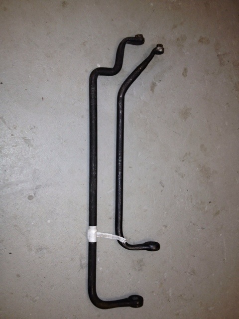
The engine work was fairly easy to do but again took a bit longer than the 1.5 days I expected (took 2.5 days). I ran into a few issues such as properly honing the cylinders and the cylinder wrench which would not work with the wings installed on the bird. I had originally built up the engine in the shop with the wings removed and plenty of room to work.

The wrench came home, I cut about 4 ” out of the length and rewelded it. I was a bit concerned because of the 50 ft lbs of torque used to tighten the cylinder nuts. It worked just fine welded up.
20111106-115950.jpg

Day one was spent getting a hone, welding the tool and replacing #2, #4 pistons. Day two was spent putting the baffles on the stbd bank, removed port baffles, and replacing the remaining pistons.

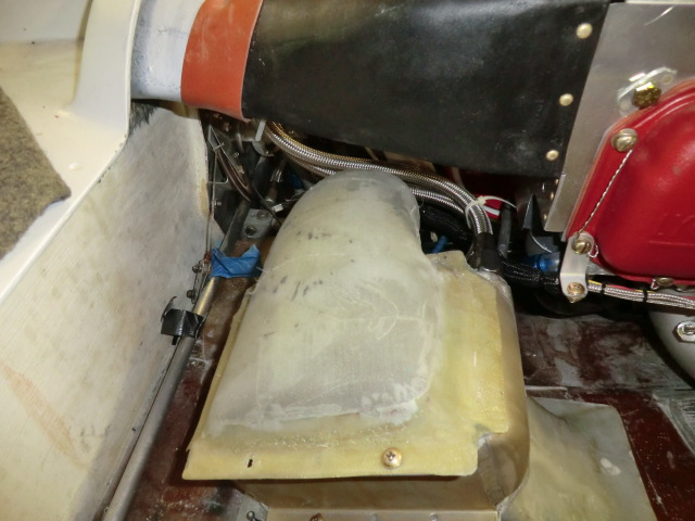
This picture shows the removal of #3 cylinder and baffles. I was amazed at to how obstructive the oil cooler is in the engine compartment. It really gets in the way of engine work. I cant wait to move it out the the wing as I did with Pat’s bird.

20111106-120018.jpg

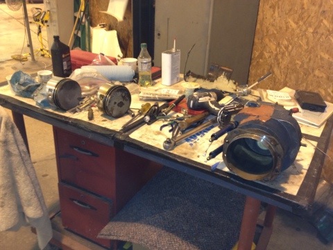
The cylinders were honed on the table with a cheap ass AutoZone honer. I had a really good one from Tony, but I didnt want to possibly affect the size of the cylinders. His hone was not the right type for a closed type cylinder.

I checked out the stores for a dingle berry type, but they were $179 and not in stock. Found a 3 bladed type hone at AutoZone for $31. For lubricant I used diesel fuel which was recommended with the hone Tony owned. The diesel lubricant worked surprisingly well and really helped cut the glaze better than using it dry.

20111106-120114.jpg

I also talked to Klaus (Lightspeed Engineering) about timing changes needed when going from 7:1 to 9.1:1 pistons. He recommended retarding the time about 3 deg (to reduce engine CHT temps) and Pmag recommended retarding the time 5 deg. The Pmag only required a jumper to be installed, and Lightspeed required the removal of the flywheel to make a slight mod on it. Hopefully the engine wont overheat due to the increased power output.

About 4 hrs more on the 3rd day to balance the prop/engine and work is done.

20111106-120202.jpg

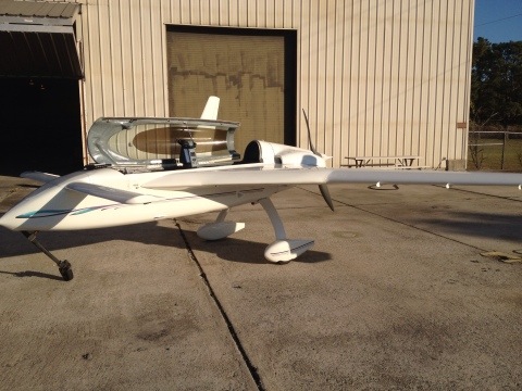
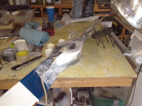
I only ran into one serious issue. Since I was upgrading the engine (piston compression) which will raise my hp from 150 hp to 165-170+? hp the 150 hp prop no longer fits the plane. My brand new Hertzler prop had delaminations on the upper blade when I pulled it out of the storage box.

Gary Hertzler was very surprised and apologetic for the problem and had me send it back for refinishing. Gary’s support is really first class…. He is also going to upgrade the prop to the latest urethane leading edges he now installs on his props.

My 150hp Hertzler prop had his original LE protection which was easily eaten up by rain. While at Oshkosh one year, I found a manufacturer selling urethane which was designed for props. I ended up cutting Gary’s LE material off and installing a urethane LE using pressure injections (what a mess). Since then, I have flown through lots of rain with absolutely no effect to the prop (other and eating off the paint). When I first suggested the improvement to Gary, he jumped right on the suggestion, researched better materials and now has it on all the props be sells. You cant go wrong with a Hertzler prop.

20111106-120330.jpg

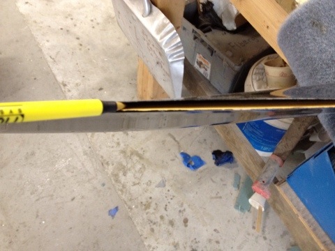
The seperation was almost 18″ long. Seperation is highly unusual and it is only a very few props were affected when Gary went to a new manufactring process (which has been improved).

Strangely, I found a few delams on my prop too due to heating by the exhause. A quick repair, a little micro and paint and it was read for balancing and test flight. Cant wait to get my new prop back to really see how the engine upgrade affects speed and fuel efficiency.

20111106-120524.jpg

Sep 28 2011

Two Days left to go

These last few weeks have been absolutely crazy for me.  I am leaving for our annual Rough River flyin in this weekend (Friday morning) and only have two days left to go.  Seems like I been doing a million things at once to try and prepare to leave.  Lots of little squaks on the plane lots to do around the house.

Later when I get back from California I will detail the work I did on the plane and catch up on the past enteries in my blog.  Here is a few things of interest for you…

I installed an “In the wing oil cooler” which is working really well.   The oil temp is now between 190-200 f at any power level.    Before I installed it I tested various locations while flying.

I also tested foam samples for heat damage prior to starting the project.

I really like the fact that it is no longer in the engine compartment.

Cowl mods came out really well.  I extended the cowls 4 inches and built in some eductors.

The wing mods came out really well too.  The upper wing air flow is terrific the bottom is fairly well too.

Today I made an iPad knee board.  It has a hinge on the bottom and one on the side, so I can write on my paper pad (as as I am used to) and it flips to the side and the iPad tilts up and locks.  I think it is really cool… and suits what I really need for flying.  I couldnt find what I wanted from any vendor, making it was the only option I had….


Tomorrow will be be mainly dedicated to preparing for my flight out on Friday.  It will start my odyssey of the cross country trip…  How exciting!


Sep 13 2011

Oil Dipstick (updated)

As you may remember I had to move the oil dip stick filler tube outside my inlet plenum to accommodate a smoother flow of air into the engine trying to cool #3 cylinding.  I found a neat idea on the web for makiung a flexible filler tube (cutting the filler tube and using a piece of hose to join the pieces) and a dipstick made from a piece of vinyl coated cable and a custom machined cap.  So I made one.

The problem is you cant see the oil level (especially if it is new clear oil)..  I used some ferrals on the cable (top) to indicate oil level.  Problem is the ferrals got stuck in the tube and again was hard to read.  So I made a second cable (bottom)  with a tube swagged onto the cable.  The idea was to try and mimic the orginal level rod as much as possible to check the oil level.

When I took the oil pan off (to fix some leaks) I found the flexible cable to be really loose and floppy in the oil pan area.  There is no way to get an accurate reading of the oil with this type of system.   Humm…???

The second attempt cable is in the top picture and the updated cable/rod is on the bottom.  Basically I took the cable idea for the flexibility and a rigid tube for readability to make bendable tube/cable level rod ….  The secret to it is a spring near the cap which holds the ridge tubes in compression on the flexible cable.

This tends to keep the level rod perfectly straight off the plane and locks as straight as possible when mounted in the plane.

here you can see the three pieces of tubes bending on the cable.   This allows the level rod to negotiate the bend of the filler tube.

When  released it is perfectly straight.  When checking the cable/rod mounted in the the plane, I found it mimics the original solid dipstick in the oil pan area so now I’ll get accurate reading of the oil level.  Only thing left to do is calibrate it when I get the  oil pan on.

Jun 02 2011

Eductor craziness

The overheating of the engine is driving me crazy.  The plane flies wonderfully well, it is super fast but I cant push it yet because of the cylinder temps being too high.

As you saw in my last post, I installed some eductors in my quest to solve the problem.

Nice shape and well built, but when I flew the plane, I only got about 15 f drop in cylinder temps at 2400 rpm but that is not near enough to allow full power operations and the cowl pressure did not significantly change (95 mph at 150 kts same as before installing eductors).     After thinking about it I wondered why my plane which also has eductors cools wonderfully well…. 

After looking at my plane

  Port

one can see my eductors are much bigger (both inlet and outlet) and the back of the cowl is compeletelyblocked off.    At 130 kts TAS my cowl has a pressure of 55 mph differental from the cowl to the static port.

  Starboard

As a last resort, I decided I would try and modify the new plane to mimic my plane.

The first thing I did is enlarge the eductors.

The next thing is to block off the entire outlet to ensure the air only had one way to escape…. through the eductors.

 Port

  Starboard.

After the mods, I went out flying.  The first thing I noted is while taxiing, I had a NEGITIVE pressure in the cowl on the ground, -10 mph and when I increased RPM, the cowl pressure actually decreased!   The eductors really worked and the more exhaust (higher the RPM) the greater the negative pressure.  

After take off the cowl pressure was 45 mph (it was around 80 mph).  The strange thing is, the cylinder temps when up VERY quickly????  what’s up with this?   Maybe it is because the engine was heat soaked waiting to take off, or the fact fact the OAT was at 95 F.  I quickly decided to land to check thing out and on downwind,  the temps had started to decrease.  Tomorrow I’ll fly again when it is a bit cooler and I can do a more extensive testing….  I got to figure out what’s going on!!


May 31 2011

Final eductor tubes are installed.

Today was spent working on the new eductor tubes.

First step is to get an idea of what the eductor is going to look like.   Some foam was used at templates to outline the inlet and outlet shapes as well as the overall length.

The shapes were wrapped with some heavy paper to use as a template to make the aluminum tubes.

The inlet of the tube is flared to smooth the air going into the eductor.

All that is needed is to mount the nut plates on the tube and I’ll be ready to test!  Tomorrow morning I’ll check out the results.


May 30 2011

Temporary Eductors

I have been having MAJOR issues with engine cooling.  I can get up to a max of 2400 rpm before the CHT’s get up to 425f.   Yesterday I decided to go flying before I cut off the front of the inlets and installed larger cowl inlets to let more air in the cylinder plentum boxes.  Sure glad I did as I found out it wasnt the inlet size, but major cooling issue is back pressure in the cowl area.    I thought I would just cut some reverse scoops in the cowl per Jerry Schneider’s SOOMA analysis (Jerry’s famous “Straight Out Of My Ass” method of problem solving).

When I woke up this morning, I realized the only difference between my plane’s cowl (excellent cooling) and the new plane’s cowl is just eductors.  I do not have holes cut in the cowls to let the air out so openings might not be necessary in the new plane, just a set of eductors..  cool!

When I went out to the club today and took a close look at the cowls and sure enough,  I notice a LOT of carbon on the cowl just aft of the exhaust pipes.  AaaaHAAAA…  the hot exhaust is basically clogging the outlet of the cowl not letting the cylinder cooling  air out

You can see on the cowl how the exhaust was backing up in the cowl and most likely causing a pressure wave not letting the  cooling air out.

I have two choices, extend the exhaust pipes or build eductors like in my plane, so I fabricated a set quick and dirty set of eductors for testing.


These are the pictures of the cowl and my temporary eductors made out of house flashing, and went flying.

Overall the minimal effort was a very good success as my temps were much better (almost normal) until one of the eductors ripped itself from the plane at 203 kts TAS and was apparently eaten by the prop at which time the temp of #3 (my hottest) cylinder again quickly started climbing up.

I think I am now on the right track and will be building a formal set of eductors tomorrow.

Apr 25 2011

Oil Cooler fitting

The cooler is test fit.  Looks good.

Apr 24 2011

Oil Cooler Glassing

The glassing of the cooler is done.  Now it is time to paint it.

Apr 23 2011

Engine Interference

Today was full of awwww shits….  now that the wiring is done, it is time to go back to working on the engine.  I need mod the oil cooler ducts and get some oil/fuel hose made up.  Shortly after starting some unforeseen miss matches showed up.

With the top cowl on I dont have enough clearance on the oil dipstick!  Shit the door wont close…


I ended up cutting the dip stick down to shorten it 3/4″

I also found the cowl hits on the front of #4 cylinder….shit.  I didnt want to cut up the baffling (dont have the time) or remake the #4 cylinder box, so I just bumped put the cowl.  Did want to do it but I had no choice. 


 After cutting the cowl out, I made a foam shape and glassed it in.  

I also needed to make a new duct for the oil cooler since I changed the intlet and outlets.  This is the shape of the old duct.


You can see how the tubes no longer match up.

I felt it necessary to come up with a inlet tube which uses NO SCAT tubing, and still allows the easy removal of the lower cowl.

The cooler was encapsulated in foam and then carved it to the right shape.  It is then covered in duct tape (black and red) to get ready for the glassing.  This is the part of fiberglass work I really enjoy because it is very artistic. 

 Better get to glassing!