Nov 28 2015

Assemble Nose Skeleton

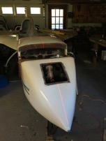
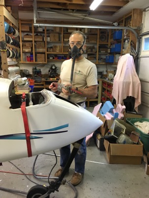
Today’s 6 hr day, was focused on assembling the nose skeleton as I call it. It is the scaffolding needed to attach the foam on the nose.

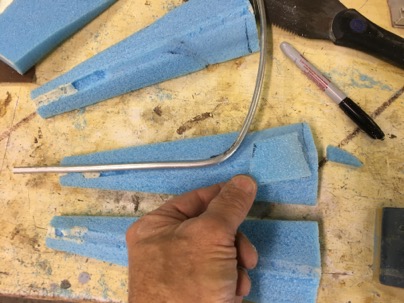
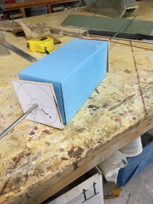
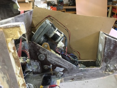
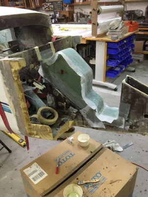
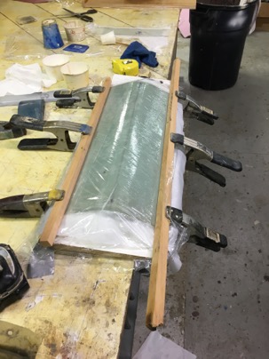
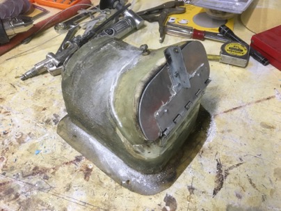
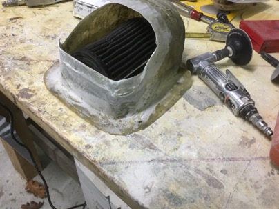
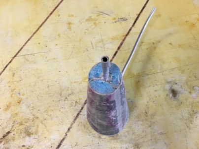
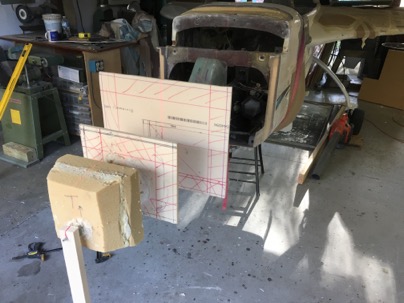
You can see the structure of the nose inlet with integrated pitot tube I made yesterday. I came up with a much better way of making this part, but I think it will be good enough for me at this point and will be saved for my next plane.

wpid-IMG_3563-2015-11-28-19-42.jpg

The pitot tube will also act as a centering pin for the tip of the nose.

wpid-IMG_3564-2015-11-28-19-42.jpg

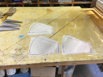
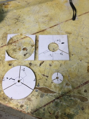
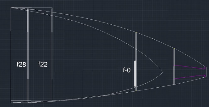
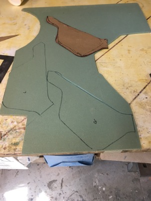
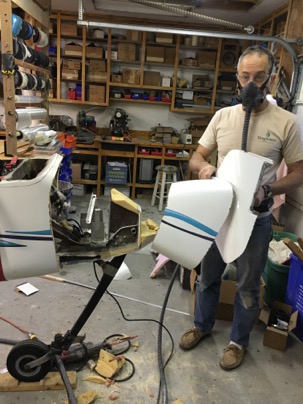
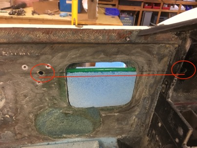
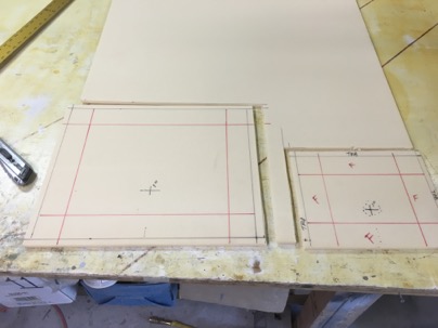
Two foam bulkheads were cut from 3/8” foam. The red marks the location of the 2” thick urethane foam cabin wall If I sand down to the inner lines, I’ll break through the foam into the cabin.

There is a mark in the center of the bulkheads for a 1” centering hole for the dowl.

wpid-IMG_35691-2015-11-28-19-42.jpg

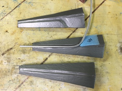
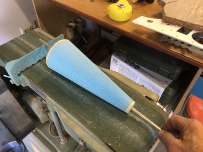
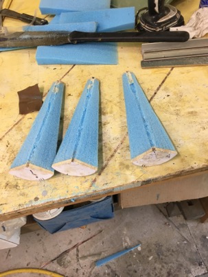
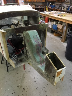
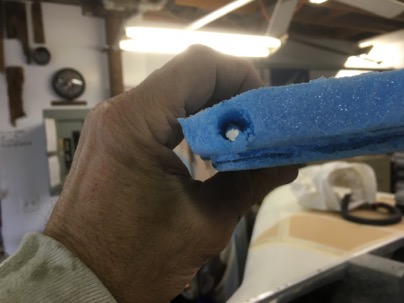
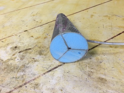
Two urethane foam blocks were cut for the tip of the nose carving. The cone was easy to use as a drill to work my way through the soft foam. Took just a minute or so.

wpid-IMG_35751-2015-11-28-19-42.jpg

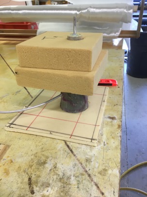
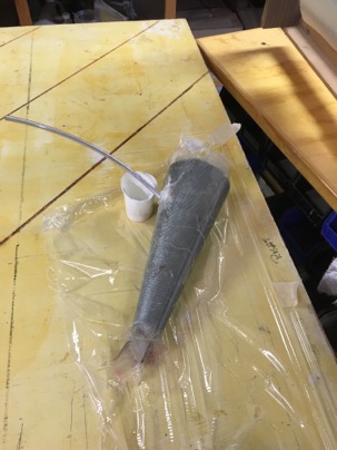
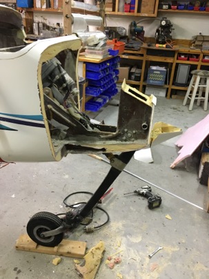
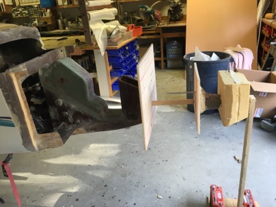
Using a 1” dowl through the centering holes, pour foam was used to glue all the components together.

wpid-IMG_3577-2015-11-28-19-42.jpg

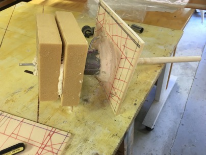
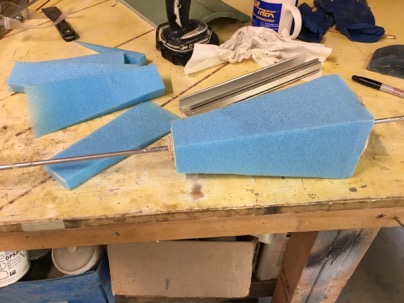
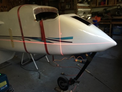
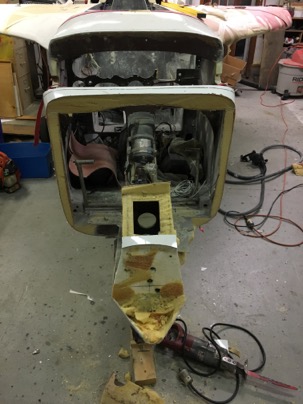
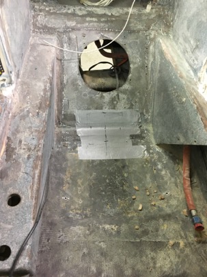
The large bulkhead was glued to the NG’s and a nose tip support was made for the pitot tube, and everything was assembled with the laser.

I have earned a great deal of respect for the laser level, and pour foam. Amazing stuff!

wpid-IMG_35811-2015-11-28-19-42.jpg

These bulkheads when trimmed will support the foam fill blocks which will be quickly carved.

wpid-IMG_3582-2015-11-28-19-42.jpg

I really don’t think urethane foam gets the respect it deserves. Known as soft, easy to damage, nasty to work with.

While removing my old nose I found when glassed in properly the foam is amazingly tough. Mine was solid as a rock even after 3 nose gear landings (2 were my fault, one a inflight emergency and 1 a gear failure). Each time I really hit hard with the nose on the pavement.

When i disassembled the nose, I found the urethane foam was as good a new. No delaminations, no crushing, extremely good attachment to the fiberglass skin. The stuff is amazing.

In the future, where I can used the urethane foam I will. It is so easy to carve, it glues well with pour foam, and doesn’t change shape like a solid block of pour foam does over time.

Lessons learned:
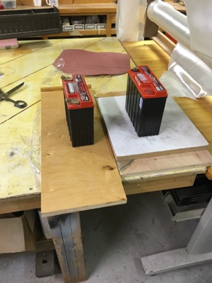
Glue the end blocks together BEFORE drilling with the cone. When using pour foam to glue blocks together, be sure to tightly clamp or weight the parts down because they will spread apart from the pressure of the expanding foam.

Nov 27 2015

Glassing the Cone

Here you can clearly see the tearing of the foam from pushing the rod though. You can also see the pitot tube and how it will be mounted.

wpid-IMG_3545-2015-11-27-19-17.jpg

I added a small defuser after the Al pitot tube to smooth the air as it flows around the tube. Why? I don’t know, just a bit anal and it was easy to do.

wpid-IMG_3547-2015-11-27-19-17.jpg

glass was cut (1 layer bid) wetted out on the table using plastic on each side.

wpid-IMG_3554-2015-11-27-19-17.jpg

The part was glassed. When the foam is removed, I should end up with a defuser cone, with 3 ribs holding a pitot tube in the center. I won’t really know the final result will be until the the entire nose is build with the cone encapsulated in the glass….

wpid-IMG_3557-2015-11-27-19-17.jpg

Lessons learned:

I glassed the cone all at one time is a major PITA and I am concerned that the glass work inside (holding the pitot in place) will not be as straight or perfect as I want it.

Next time I would glass the ribs separately on the table (nice and straight), then flox the ribs to the pitot (using the foam a guide). Cure. Paint the ribs Black.

Mark and cut the ribs to the outside of the foam cone. Reassemble the cone, add a small amount of micro to the end of the ribs then glass the outside with carbon.. I would end up with a cone that all black.

It would add a few more steps but the end result will be perfectly straight ribs in the center and fillets on all the support ribs… and a much better looking product.

Build time 3.5 hrs.

Nov 26 2015

Nose Inlet Construction

The inlet will consist of 3 pieces of foam cone (expanding the air at 7 deg per side) holding the pitot tube in the center. The inlet will feed a preheater for the cabin. It is an idea I captured from the Cozy Girls and wanted to make it with out the work and the pitot heat they put into their system.

Templates were glued on to some 1/4 wood, I used the band saw to cut them out and to slot them (for cutting the foam.

wpid-IMG_3512-2015-11-26-18-57.jpg

A foam block was cut. A rod was PUSHED through the foam, then using the rod as a guide, the two wood templates were glued onto each end of the foam,

wpid-IMG_3511-2015-11-26-18-57.jpg

A quick trim with the band saw,

wpid-IMG_3515-2015-11-26-18-57.jpg

Belt sand the cone with to the wood template,

wpid-IMG_3535-2015-11-26-18-57.jpg

Using the slots as a guide the remaining wood was cut which split the cone into 3 equal pieces with a hole in the center. The only issue was I should have drilled the hole instead of pushing a rod though it. The rod caused tearing of the foam at one end instead of a nice clean hole.

wpid-IMG_3542-2015-11-26-18-57.jpg

Lesson Learned:

Drilling hole first, THEN cut out the foam block, then mount the templates, before shaping.

Nov 25 2015

Planning the nose

Today was planning for the nose modification. Using AutoCad, I drew it out till I was happy with the overall look

You can see the old nose and the look of the new nose. There is also cone shaped area in the nose.

wpid-nose-2015-11-25-18-29.jpg

Notice the cone shaped area in the nose. This will be the inlet for the cabin pressurization system, air preheater for the new oil heat system and hold the pitot tube.
.

Nov 24 2015

Noselift cover

I want to completely seal the nose lift area. This is a great opportunity too seal every holes since I have the nose completely opened up.

After making a quick cardboard template,

wpid-IMG_3482-2015-11-24-18-50.jpg

Foam was cut for 1/4” in sides and 1/8” top.

wpid-IMG_3490-2015-11-24-18-50.jpg

5 min epoxy the parts together, then glass

wpid-IMG_3491-2015-11-24-18-50.jpg

then 2 layers of BID.

wpid-IMG_3561-2015-11-24-18-50.jpg

My only mistake was I should have only used 1 layer of BID. The part came out at 9 oz!! yikes. Next time I’ll use 1 layer of carbon.

Nov 22 2015

Week 2 report

Hours worked: 37.3        
Total hours: 71.8

Notes: none

Nov 20 2015

Nose removal

Today, did something I wanted to do for years, but was truly reluctant to get started on. I had even delayed placing my order for foam and kept procrastinated about getting out the saw to get stared with the work. i have reached the stage where I need to just get it done.

This is how it looked.

wpid-IMG_3422-2015-11-20-20-16.jpg

When I shot the laser, I found the nose was actually constructed 1.5” below the point it should have been. The proper point is at WL 8” but was actually set at WL 6.5”

wpid-IMG_3423-2015-11-20-20-16.jpg

It really didn’t matter much because it will all be removed and rebuilt properly. With a heavy heart, I got started.

wpid-IMG_3449-2015-11-20-20-16.jpg

You definitely want to protect yourself from the dust generated from this urethane foam. I really like my hobby air system for supply clean air. A mask in this case would have worked just fine.

wpid-IMG_3470-2015-11-20-20-16.jpg

Total removal only took about 15 minutes. Wow, I could chop the whole plane up in an hour to so….

wpid-IMG_34731-2015-11-20-20-16.jpg

Not much left of the old nose.

wpid-IMG_34721-2015-11-20-20-16.jpg

Later in the evening I actually felt good about cutting the dam thing off. I am totally committed now and have now gone as far down the rabbit hole of total destruction with this plane as I had planned. Now to start with building her back up. After clean up the cut lines in prep for the foam installation, i will build a cover for the nose lift system to seal the area against air leaks since I have easy access to the nose lift now.

Nov 19 2015

First glassing

Today I did my first glassing in a long time. It was actually quite satisfying.

This a a jig I made to curve a piece of 3/8” foam for a foot rest/storage area for the back seat passenger.

wpid-IMG_3418-2015-11-19-20-17.jpg

Under the wood is 3 layers of BID which has a 3/4” joggle in it so I can make a panel for the back seat electronics. You’ll see it later when I installed it behind the passengers headrest. I am moving the battery from the front to the back of the plane to save the weight (9 lbs) of battery cable. The tools normal stored in the headrest will be moved to the front of the plane.

wpid-IMG_3419-2015-11-19-20-17.jpg

Nov 17 2015

Prepping the cabin for glassing

After removing my pressurized oil heat system, I decided I NEED to do some glass work. I am tired of stripping and sanding and taking the plane further and further down the path of disassembly. I need some creative time with the bird..

This is the normal canopy hatch door that I am closing off. See the red lines. It is a wire chase I am installing for an accessory mount for my iPod at the left end. I will wire power and a stereo input thought the case. I hate to see wires and this is an easy install.

Draw a slight line, drill a hole at each end, drill a hole in the door flange and auger out the foam in between.

wpid-IMG_3406-2015-11-17-18-04.jpg

After fitting a piece of foam to close the door, drill a hole though it along the level line, Split the foam along the drill hole, stick at soda straw as a conduit, micro in the bottom and top pieces of foam and glass the door. Took all of 10 minuets to prepare

wpid-IMG_3405-2015-11-17-18-04.jpg

This is the airbag for the engine (holds the air filter).

The Door on the box was a later addition which I used to increase the cabin pressure when flying though rain.

Opening the door would to raise my normal low -50 mph cabin pressures to +5 mph cabin pressure. All the water stopped entering the cabin. I could actually feel the vents in the plane reverse direction. It is low cabin pressure which sucks ion the rain and cold. Adding more seals is just trying to fix the symptoms of the problem, without addressing the root cause.

The only drawback to my original test design was it made the cabin incredibly loud due to power pulses from the induction system having a clear path into the cabin.

wpid-IMG_3409-2015-11-17-18-04.jpg

I have a new type cabin pressurization system I have designed will address two things. Pressurization of the cabin, and improving the climate control if the cabin. If this system is successful I will duplicate it in the cozy. I learned what I needed from this successful experiment so time to be removed.

wpid-IMG_3410-2015-11-17-18-04.jpg

The door addition was cut off and box will be returned to it’s original design. Weight removed. 8 oz.

wpid-IMG_3416-2015-11-17-18-04.jpg

An area was prepared for glassing. I will be the cover for where the floor where the of the ADS-b antenna and ground plane will be installed.

Nov 15 2015

Week 1 report

Hrs: 34.
Total: 34.5