Dec
14
2012
Engine Done!
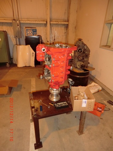
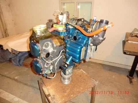
The engine is now fully assembled.
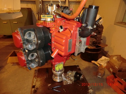
It really looks great now! Much better than before. I left off the exhaust and intake systems as this work will need to be done on the plane.
Read for the engine mount!
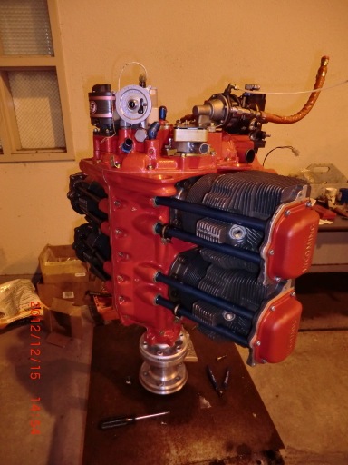
The engine is now fully assembled.
It really looks great now! Much better than before. I left off the exhaust and intake systems as this work will need to be done on the plane.
Read for the engine mount!
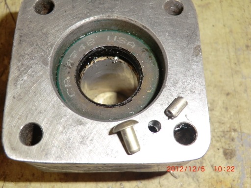
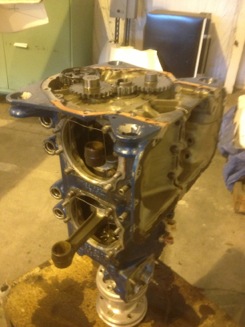
Today starts the big day! Engine reassembly. The only issue which was found with the engine was the crank journal and rod bearing were ground down a few thousands of an inch. The engine had 770 hrs on it since the last time I overhauled it, so a little work was to be expected.
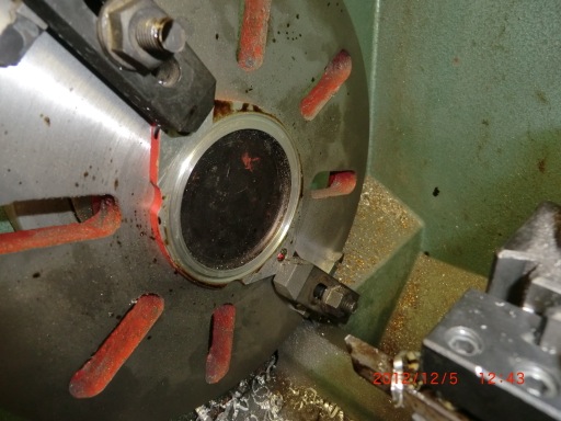
The crank was put on the stand for assembly.
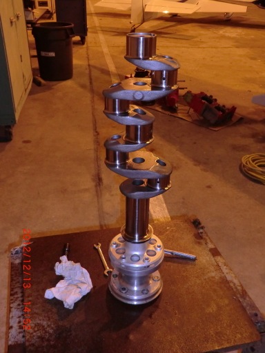
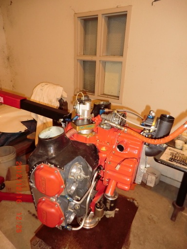
By the end of the day, most of the hard work had been done. I am working slow and easy trying to pay attention to everything I should be doing and not rushing the experience.
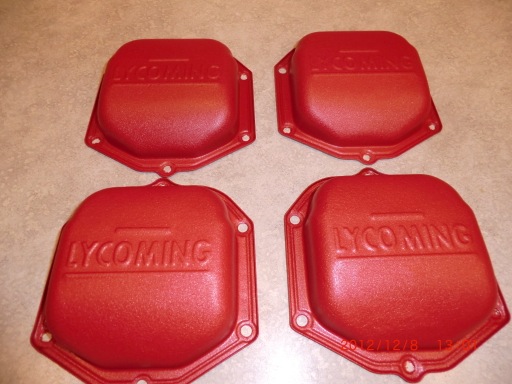
Today I received the valve covers from the power coater. I had them coated with crackle red.
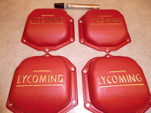
Using a gold marker paint pen really sets off the lettering on the covers. Nice!
One of the good things about doing this engine overhaul is that I can renew my efforts to get rid of oil leaks. I will replace all my self made oil hoses with the newer teflon with SS brad type and again try to seal the gaskets in such a way to reduce oil leaks. As most owners, it is our goal to have ZERO oil leaks. With this old lycoming technology it is a bit difficult to achieve.
Where possible, I have made a few mods (thank your experimental aviation!) to reduce oil leakage points. A search on the internet resulted in the design guide from Parker O-ring company and I was able to learn quite a bit about how to properly machine an o-ring grove. The ones which I originally machined into a few parts were not correctly made. This may be why my first attempt at sealing was less than successful.
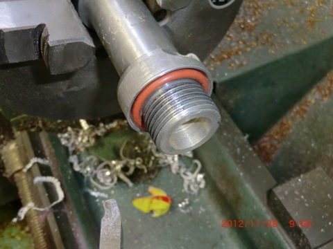
First I corrected the o-rings groves machined into the oil dip stick extension tube I made for my down draft cooling plentums.
Next it was machining an o-ring grove into the oil temp sensor to replace the copper crush seals on the B&C oil filter.
This is the oil temp probe with the 1/16” Viton o-ring. A little research shows Viton to be one of the best oil ring materials for the fluids in our planes. For oil, 100LL, brake fluid Viton has the best chemical properties. I am glad I looked this information up as the old Brock gas caps o-ring seals always give me problems with sealing. Now I know why, I was buying the wrong type material for the o-rings and mo-gas would cause them to swell. I have to go to the hangar tomorrow, so I’ll get some new ones for the bird and replace the ones which are on it now.
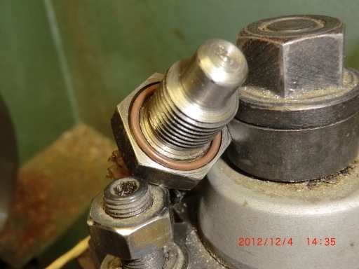
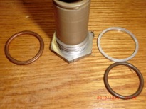
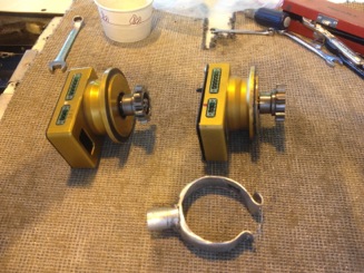
For the vernitherm, you can see the crush ring on the left and the o-ring/spacer ring on the vernitherm
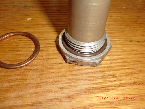
Crush rings do work… sometimes, but I don’t trust them. Since there was limited room to work with on the vernitherm , a pressure ring was machined (to allow proper crush of the o-ring) to contain the o-ring.
I was concerned about the proper positioning of the the vernitherm element as It has to be the right distance from the seat to work properly so I didn’t want to machine the cap (even if I could have).
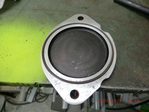
For the accessory case, I tapped and installed a plug in an unused oil gallery used to mount the pump for the controllable pitch prop governor..
This way the gasket should not see any pressure at all. Again, no o-ring could be used
.
For the vacuum pump pad, there was a small port which is used for lubrication of a “wet” type vacuum pumps. Since we are using “dry” pumps this oil gallery again could be plugged. I used a large rivet, cut the head off, and inserted it into the hole with sealant and crushed it place to make a solid aluminum plug to keep oil pressure from being applied to the vacuum pump gasket.
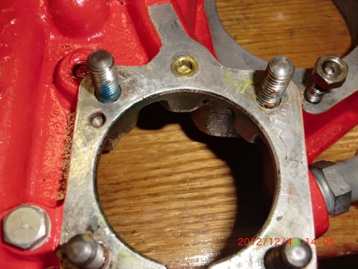
Lastly, an o-ring grove was machined into the plate used to seal the unused mag hole,
No gasket is needed. Such a simple operation! I don’t know why the covers dont come pre-groved.
I only hope that the effort into making these mods makes a difference on the oil leaking on the engine. Should be interesting to check out when I get the plane back into the air.
*Update: Feb 2012- The mods were successful! I didnt have any oil leaking from any of the changes I made.
I did find oil leaks at the flare fitting of the hoses. Apparently, the AL fitting, even though they are anodized, can be easily scratched or damaged thus causing leaks. I had to lap the end of the hoses into the fitting to eliminate the scratches. In the future, I’ll only use steel fitting for any oil/gas line on the engine.
Today I got the engine hoist and prepared for the pulling the engine from the plane. Finally it is off.
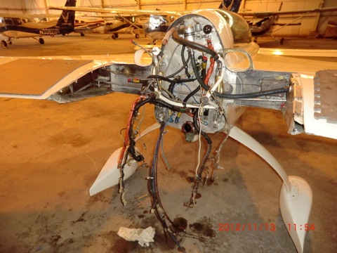
Next step is disassembly.
I started off going to the metal shop to pick up the material to make a case splitter. An aircraft engine does not use a gasket between the case halves. It uses a sealant which essentially glues the cases together. You MUST use a splitter to get the case apart.
I had come up with a workable design and made a case splitter years ago and after using it, was loaned it out to a buddy. Unfortunately, he lost half which required me to have to make a replacement.
Surprisingly, when I googled “lycoming case splitter” I only came up with one hit on how to make one. It was my OWN website! I had completely forgotten that I had posted pictures and details on the web. Making a new one was easy and only took a few hours to complete.
After building the splitter it was off to the airport to begin disassembly of the engine. I made a quick engine stand to to hold the engine up vertically, and got to work.
By the end of the day, the engine was torn down and ready to be split. I’ll do that tomorrow.
I think I am going to strip off the blue color and repaint the engine in red. I need a change.
![]() Engine, LongEZ Repair, N29TM | Nick |
Engine, LongEZ Repair, N29TM | Nick | ![]() Comments (0)
Comments (0)
As soon as I returned from Myrtle Beach, I installed the rebuilt fuel servo on the plane and took her up for a test run.
Tweedy started better than ever and I now have plenty of power and can easily get 2700 rpm. I did a full power run and got up to 182 kts true at 1500 ft. Sweet.
The only problem is the vibration issue hasn’t changed. Still got it.
I have been fighting this issue since my return from my “western” tour trip. I have rebuilt the the electronic ignition systems (overhaul of the Pmag, replacement of wires and coils), replaced the Lightspeed coils, replaced the plugs, replaced one of the cylinders, replaced the engine mount, overhauled/replaced the hydraulic lifters, did compression tests, wobble test, checked everything I could think of, had the engine off the airplane twice, and nothing has made a difference.
The engine went from running great to having a noticeable vibration in one night. When I landed in Santa Fe, it was running great. When I took off the next mooring, I had a vibration which I instantly noticed. After almost 3 months of trouble shooting, I have finally made the decision to just take the engine off and rip it apart to have all the internal components inspected and rebuild the lower end.
If after rebuilding the engine if I still have a vibration, I will know there is absolutely nothing wrong with the engine, it will not self destruct on me and I will just have to live with the vibration.
Tomorrow let the fun begin.
Day was an interesting day for in my fruitless search for the engine problem.
I had completed four flights today. What I discovered was I could not get any power above 2480 RPM. When I went full throttle engine actually started running rough and backfiring. I called Klaus at Lightspeed to discuss the problem and he stated focusing me and on the fuel flow. It is too low. I am only seeing about 9 gph and at full throttle and it should be up to 12 gph. Humm, maybe that is one of the problems.
After talking to Klaus, I decided to take it up for another test flight. As I was climbing out the fuel flow initially I went up to 11.8 gallons per hour, then the fuel flow dropped to 7 gallons per hour and I started losing power. I declared an emergency and they had to divert a airliner landing to get me on the ground in a hurry. What fun! NOT!
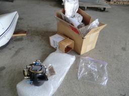
I called Airflow Performance back (which built my fuel injection system,) talk to the owner Don, and we decided I could bring the system to Greenville testing on Tuesday. I had already cleaned two filters, but was unaware that there is a third filter in the system.
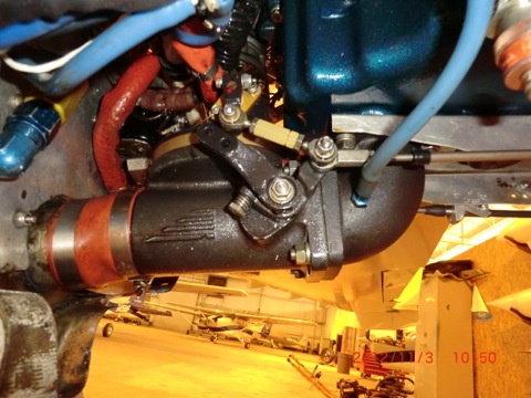
This is the fuel servo (1 filter in it)
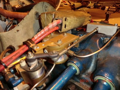
This is the flow spider (it also has a filter).
Cant wait to see what the initial test results show up.
Today started out thinking about my engine vibration issue while lying in bed. What could be causing it?
I have investigated everything I could think of during the last 2 months searching for an answer to a problem no one but me would notice.
I recalled starting the engine on Sunday and it seemed to have stared running smoothly, then a few moments later I noticed the sound had changed a bit. A sort of popping sound. Very light pop or harshness to the exhaust , but different then what I remember. Hum, this sound be could it be valve related? Recently I was thinking the sound had changed a bit from what I think is normal. Instead of a smooth sound it sounded like it had an exhaust leak or something (of coarse it doesn’t). What if the valves were not properly opening/closing at the proper time? Is it related to the heat up of the oil affecting it somehow?
The only components which would affect compressions (and thus the power pulses) would be a broken ring (doubtful), something particle trapped under a valve seat or a hydraulic lifter. The lifters use oil pressure to expand a tiny hydraulic cylinder which is used to “self adjust” the valve clearances. It is a much better system than I had with my old Lycoming 0-235 where periodically I would have to manual adjust the valves. Theoretically, the valves will never need to be adjusted and always be perfectly set. Think of the old days when you had to get your brakes adjusted on your car and now they are self adjusting.
Todays goals were to
First, remove my PMag electronic ignition and ship it back to the EMag Air for upgrade and testing to rule any possible ignitions issues out of my trouble shooting efforts. Brad will make sure they have the latest software and upgrades done on the PMag while the plane is down. I ordered new wires to replace my spark plug leads and a coil too.
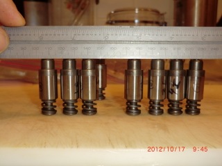
Second was to remove all the lifters and carefully check them out according to the information I found on the web.
It is not hard to remove the lifters and only took a few hours. While cleaning them, I noticed #2 exhaust lifter was very sticky as compared to the others. All the other lifters have a smooth in/out and in rotation action and fit snug but not tightly.
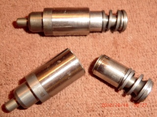
#2 was sticky and tight going in and when rotated felt gritty or when a bearing hangs up when rotated. Strangely #2 cylinder is the same one I replaced due to scoring on the inside cylinder walls. Could it be related or did the lifter decide to score itself in sympathy with the cylinder? Doesn’t matter because the cylinder is gone and this little puppy will be gone too. I finish carefully examining the rest of the lifters and order any new ones I need tomorrow.
I also tested them for a “collapsed” lifter and all was good.
Thinking about it, a bad lifter does make some sort of perverse sense. If it is sticking it could respond to weird stimuli such as pressures or if the oil temperature is hot or cold causing it could hang up and work or not. Sticking would not affect my compression or engine power (to a great extent) but would affect when the valves opens or closes. The popping sound could be the valve opening at the wrong time (too soon or too late) in relation to the other cylinders.
Too bad it will be a while before I can test the plane again. I have to wait for my new lifter, an my ignition upgrade to arrive before I can assemble everything to fly again. Fortunately, both should both arrive about the same time.
While waiting for parts, I plan to start installing my fuel probe system in the plane in preparation for the arrival of the programable fuel gauge. It will be so nice to have an accurate readout on the dash of fuel levels.
After leaving Oshkosh this year and starting my trip, Lee and I flew to Denver together (flight of 2). The first leg ended up being longer than expected due to some bad weather and I started becoming concerned about the fuel level. Naturally some the junk in the back of the seat fell in front of my stbd fuel sight glass. Crap, I could just see the level before it dropped below my stuff. So I timed my tank based on usage to switch to the port side at the last minute and decided on a “gotta land point”. Naturally, everything was fine, but I decided then and there, this is the last trip I’ll fly without dashboard fuel readouts.
The whole reason I invented the probe and worked with Princeton Electronics who developed the electronics was to see the fuel level in MY plane and I don’t have them installed yet. Finally, I’ll have the fuel readouts I have dreamed of for so many years.
I wanted to show you the greatest thing for wiring a composite plane I have ever come up with.
The big problem with wiring one of our birds is how do you secure the wires to the structure. You cant just put screws in the side of the plane. Securing wires is a big issue…
I came up with a great way to do this which weighs almost nothing. I call them zip tie loops (ZTL)s. After you fabricate them (which takes very little time) you can secure them anywhere on your structure by just gluing them in place with a little bit of flox. They are so light you dont even need to secure them or hold them in place while the floxis curing. Just wet the back side and postion. Once cured, they will self destruct before they will come loose.

Just stick them where ever you need to secure a wire bundle. I must have 30 or 40 of them in the plane now.
ZTL’s are made by taking 3 layers of wetted glass and laying them over a rod or some square material (1/4″ x 1/4″ I would recommend at least 1/4″ high. In this picture I just used some scrap 1/4″ delron rod I had handy. In this case I tired two different tests. Case one, 1 bid, 1 carbon BID (fair) and case 2, 2 BID and 1 carbon (better). I dont think the carbon helped much so I would just recommend 3 or 4 layers of BID.

I like to use the LoVac method to make sure there is a nice tight loop in the strip.

After curing I used my radial arm saw to cut the slots in the long strip and a pair of scissors to separate the loops. A little paint and they are ready to install in the plane.

Here is some ZTL’s that I am spraying black to match the interior of the plane.

Quick and EZ.
Today was a great day. I drove up to Summerville this morning to look at a 1995 Mercedes diesel. It turned out to be a bust… I then flew over to Mt Pleasant to meet up with Mike to fly together.
He has a beautify acrobatic plane a IO-360 (180 hp) christian eagle. Mike is taking his wife up for her fist flight.

I bet she was happy when he did a quick barrow roll!

This is a great shot over Charleston with the new bridge in the background. The crazy thing he kept asking me to slow down. Mike had his plane firewalled at 130 kts, so we slowed down to 125 kts (2700 rpm) and I was only turning 1900 rpm. When I left him, I firewalled my plane and quickly pulled away from him. I never felt so fast!

While I was landing, I noticed the lock gear down light was not lite and I could not cycle the gear down properly (about 1/8 turn from full down). This seemed strange to me and I felt the over-center device hadn’t engaged so I called the tower to let them know I had a gear warning light. Sure enough when I touched down, the nose started to collapse. Sort of progressively dropping instead of a quick drop, BANG. I was almost stopped with I hit the ground. The plane was moved off the runway, I lowered the gear (this time it locked) and taxied back to the hangar.
Minutes later the towered called me. Within 30 minutes the S.C Flight Standards Office called for an update. If only the rest of the federal government worked as well as the FAA.
I told the FAA there was no problems, the plane wasn’t damaged, (it wasn’t) and everything was ok (it was) then immediately started tearing into the nose to find what what going on. I was lucky this time, I only ground about 1/4″ off the nose bumper!

I removed the nose gear assembly and found the gear had stripped. It was tuned 180 degrees (just flipped over) and it was as good as new. Reassembled the plane, test all and decided it was an anomaly and watch for any warning signs in the future. Another new experience to learn from.

One good thing about this event is that I now think I can install a electric nose lift in the plane. I always thought there was not enough clearence in this area, but after disassembling everything, I now believe it can be done.
After fixing the plane, I stopped by to see a bunch of my retired navy officer friends at the yearly RINK roast at the Elks Club. It was great seeing some of my old buddy’s.

Overall, quite a busy and exciting day!