Category: LongEZ Upgrade

Jan 19 2018

PMag Blast Tube

A requirement for a PMag installation is the addition of a blast tube on the base to assist in keeping the unit cool. Since PMag does not sell an adapter, it forced me grab some scissors and create a template. It took little time and is very light weight.

Here is two orientations I needed for both of my PMag.

IMG_9049-2018-01-19-16-21.jpg

Here is a very easy design to cut and bend the adaptor which insures the air is directed into the cooling grill on the bottom side of the unit.

IMG_9037-2018-01-19-16-21.jpg

After bending the metal (.015” AL) a tube was riveted on and all was sealed with a bit of RTV.

IMG_9048-2018-01-19-16-21.jpg

Enjoy.

http://nickugolini.com/blog/wp-content/uploads/2018/01/BlastTubeforPMag-1-19-18-2018-01-19-16-21.pdf

Jul 02 2017

Transponder Antenna Test Complete

Here is an update for the angular slot transponder antenna.

My second test was conducted at 1200 ft, 18 miles from Charleston International. At this distance and altitude ATC had no problem receiving my transponder squawk.

Finally, I today I returned from a 1.5 hr cross country trip at 7,000 ft with the goal again testing the plane on a real trip. Again, no issues or complaints from ATC. At one point I was 55 miles from the receiver again with no issue noted from ATC.

Although my current installation location ideal due to the fact it is in a small cardboard enclosure and just one foot in front of the existing ground plane which covers almost the entire bottom of the cabin it still seems to work perfectly. If anything, this would be a worst case installation, but it works.

I know this antenna will be the one I install in my next plane.

Next Up, I’ll connect a test antenna for ADS-B in the hell hole (again, the few places in the plane free of ground plane paint).

Jun 18 2017

Annular Slot Antenna

Yesterday I tried out a remarkable transponder/DME/ADS-b antenna I made. It is called an annular slot antenna. Very easy to build out of brass sheet stock. I never heard of this type of antenna. Apparently they are used extensively and most military aircraft use this type of antenna because they are no drag and totally flush on the surface.

Jack Wilhelmson told me about this antenna (he made one, but not tested) and gave me the drawings/materials, so I thought I would try making one for the plane.

Here is the fabrication drawing. Units are in MM, and be aware of the funny looking (European) “1” they look like a upside down V. If you look at the date of the drawing, you’ll see what I mean.

http://nickugolini.com/blog/wp-content/uploads/2017/06/annularslotanttena-2017-06-18-12-58.pdf

The write of of the antenna…

http://nickugolini.com/blog/wp-content/uploads/2017/06/AnnularSlotantennatheory-2017-06-18-12-58.pdf

It was easy to solder it all together, and I had an extra BNC panel connector for the cable. It took about an hour to fabricate.

IMG_7494-2017-06-18-12-58-2.jpg

It is so simple to make I wondered if it would work at all given that it does not have a large ground plane, and is very weird looking.

TESTING:
To test the antenna, I temporarily ran a jumper cable from my existing transponder antenna location to the new antenna and went flying. At 3000 ft, I flew outbound from KCHS. At 25 miles, the transponder reply to ATC became intermittent. I was told by ATC that is about normal for most airplanes at that altitude which was very good initial test result in my mind. As soon as I banked around to return to the airport they immediately picked me back up again. So possibly, the signal was being shielded by the engine and the extensive ground planes installed in the aircraft.

I plan to leave the antenna connected in the plane for a while so I can test it on a real cross country flight to see if it performs as well as my existing external antenna. If it does, then I will definitely be using this design for my transponder/ads-b antennas in my future airplane. I would use it on my plane, but the entire bottom of the fuselage is painted with ground RF paint so I have to stick with my existing antennas.

This design will save a bunch of money, and I don’t have to worry about installing large ground planes for external antennas. Low drag transponder antennas are $80-$160 for a shark fin type. This one is no drag. One could hollow out the fuselage foam in the put a layer of glass to seal the foam and flush mount them on the interior of the plane and you would have no antenna exposer at all on the exterior.

Best of all you can build 2 of these antennas (for transponder and ADS-B) for about $25 with brass you can buy on amazon or a local hardware store. I am amazed I never heard of the design.

Here are some pictures of the build.

A BNC panel receptacle number 31-203-RFX about $4.00 Obtained at a local electronics store.

IMG_7503-2017-06-18-12-58.jpg

Trim off a bit of the unneeded insulator to help with the fabrication:
IMG_7504-2017-06-18-12-58-1.jpg

You could screw or rivet to hold the connector to the ground plane, I just soldered it.
IMG_7505-2017-06-18-12-58-1.jpg

After soldering on the center rib, you attach the side supports. A cleco makes it easier to hold the rib in place.
IMG_7506-2017-06-18-12-58-1.jpg

IMG_7507-2017-06-18-12-58-1.jpg

Attaching the electrode is easier if you pre-wet the areas with solder, then hold the pieces together to connect the parts. After the center electrode is done, solder the side supports to the ground plane.
IMG_7508-2017-06-18-12-58-1.jpg

Done! I used a piece of card board to make a small enclosure case to protect the element and for testing.
IMG_7509-2017-06-18-12-58-1.jpg

Oct 07 2016

Hurricane Matthew

As of right now, Friday, 9 pm the weather in Charleston, SC hasn’t been too bad.  Lots of steady rain thorough out the day, since 1 pm.   I would say 10-25 knt winds.   

Hurricane Matthew  is located somewhere between Jacksonville FL and Savannah, GA.  The forecasters are still not sure if Matthew will pass east, slightly off the coast of Charleston or slowly turn out to sea resulting in a direct hit to Charleston with the eye wall.     The eye wall is where the winds are the strongest, don’t cha know.    

During 1989 Hurricane Hugo, the eye of the storm passed directly over my house in Charleston.  It was really creepy to have the winds blasting from the east, then dead calm for about a few minutes.   You could walk outside, no rain or clouds and the stars clearly visible.   Ten minutes later the winds were blasting from the west with the same intensity.  The two strong hits wind events, 180 degrees apart resulted in lots of damage   Needless to say, I hope this one stays off the coast.   

The real fun in Charleston will start about 2 am (tropical force winds).  At 5 am we will get the the real hurricane force winds (>74+ mph).    5 am – 7 pm will be the worst period for the storm.      

Fortunately, I live inland about 14 nm NW of the nearest coast line and am surrounded by dense tall woods on high lot with no chance of flooding.    When I built the house, I engineered it with the Hugo experience in mind, so I am actually a bit excited, eager but also apprehensive about the next few hours.   Sort of like your first flight in your home built airplane. How good are your building skills and will your survive the experience intact quickly races though your mind as the throttle is advanced.     

As far as my airplane, it is still safely tucked in my garage.    Talk about crazy good fortune….  

I have just completed a year long upgrade on the plane and had planned to take it to my hanger THIS weekend and reassemble it.    

wpid-IMG_5033-2016-10-7-21-05.jpg

wpid-IMG_5174-2016-10-7-21-05.jpg

I am glad the last minute delays of life kept the bird home a bit longer than I had planned.  My hanger at JZI is probably as old as I am and I dont have a lot of confidence it surviving a really bad storm. The only thing that matters at the airport is the wings and if they are damaged it is an easy repair, and heck and they needed to be repainted anyway.  No big deal.  

Time to close.  I still have power and internet and want to make of the most of modern technology watching Luke Cage on Netflix before being returned to the middle ages using candle light at night to read a paper book for entertainment.

Apr 11 2016

Building Tips: Finish Mounting Cans

Now that you have determined the position

Next cut a piece of angle (thin, purchased at Home Depot) with the short bases the width of the separators in your panel.

UNADJUSTEDNONRAW_thumb_284c2-2016-04-11-18-30.jpg

They will end up looking like this

UNADJUSTEDNONRAW_thumb_284c6-2016-04-11-18-30.jpg

here you can see if you shorten one leg, they will nest on top of each other for a very narrow stack. In my case the separation between the radios is about 1/4”. In this case there is no way to use a screw and nut on the bracket to the radio can. It will have to be riveted.

UNADJUSTEDNONRAW_thumb_284c7-2016-04-11-18-30.jpg UNADJUSTEDNONRAW_thumb_284c8-2016-04-11-18-30.jpg

Using the hole location on bracket calculated, mark a line on the bracket,

UNADJUSTEDNONRAW_thumb_284ce-2016-04-11-18-30.jpg

verify the location

UNADJUSTEDNONRAW_thumb_284cb-2016-04-11-18-30.jpg

insure it is square, mark, remove the bracket and rivet it to the can.

UNADJUSTEDNONRAW_thumb_284cc-2016-04-11-18-30.jpg

once it is the bracket is riveted to the can, you can clamp the can to the instrument panel, Put some heavy duct tape around the hole and insert your instrument to center in the instrument panel. The duct tape will protect the finish of your instrument.

UNADJUSTEDNONRAW_thumb_284cf-2016-04-11-18-30.jpg

with the radio in place, clamp the bracket to the panel and drill the mounting holes.

UNADJUSTEDNONRAW_thumb_284d1-2016-04-11-18-30.jpg

remove the can, install nut plates on the back side of the mounting brackets and reinstall. Then mount the can and check it out. Here you can see I added a strip of AL prior to drilling to simulate the mounting bracket which will be on the radio next to it since the brackets are nested together as shown above.

UNADJUSTEDNONRAW_thumb_284d0-2016-04-11-18-30.jpg

in my case, all instruments were level (perpendicular to the instrument panel) and within .010” of each other. A very easy install for a tight panel.

UNADJUSTEDNONRAW_thumb_284d3-2016-04-11-18-30.jpg

UNADJUSTEDNONRAW_thumb_284f1-2016-04-11-18-30.jpg

The final result. Nice….

IMG_5033-2016-04-11-18-30-2.jpg

Apr 05 2016

Building Tips: Mounting Radio Cans

The first time I mounted my radio cans resulted in a terrible job. It is hard to hold the cans perfectly aligned (horizontally, vertically and angularly), mark the hole and drill it for screw/nut.

Here you can see how far my first attempt was off. At the end of the can (where the wires attach) it was about 3/4” off. I decided to throw them out and start anew with a little thought as to the best way to do it.

IMG_4303-2016-04-5-17-07.jpg

IMG_4308-2016-04-5-17-07.jpg

The issue really is you want to mount the cans with a certain amount of exposure so all the cans stick out exactly the same amount and the are perfectly level and straight behind the instrument panel. I dont feel using screws on the cans is the answer. Yes, you can file the holes and make adjustments, but you CAN NOT do that if the radios are really close set. My radios are 3/8” distance apart. I can’t even rivet braces to the front panel and use nut plates and screws.

Here is the method I successfully used.

You’ll need a dial veneer caliper, Gorilla tape (nice and thick at .025”) , Alum angle (from Home depot), screws, nut plates and rivets.

File the top of your can hole and one side straight as reference lines. Using these sides as a references, file as needed the two remaining sides till the opening is about .040” bigger than your radio face plate.

IMG_4305-2016-04-5-17-07.jpg

Put strips of the gorilla tape on the edges of the holes. This will not only protect the expensive finish of the radio, but center the radio in the opening. File the hole till the radio fits nice and snug.

Drill holes in the instrument panel where you intend to put the mounting screws. I used a #XX drill for the clecos. I like to drill a minimum of 2 holes per radio or for a stack of radios I drill 3 holes.

IMG_4302-2016-04-5-17-07.jpg

Next stick a drill bit in the hole to measure the diameter of the hole.

IMG_4306-2016-04-5-17-07.jpg

Measure the distance from the face to the edge of the drill bit

IMG_4307-2016-04-5-17-07.jpg

Now decide on the amount of exposure you want on the radio. In my case I wanted .050” because my GRT EFIS has a 1/2” exposure.

Because of my narrow openings I had to stack the support brackets.

Location to drill the bracket rivet holes = (Exposure desired + panel thickness) – ((Hole dia/2) + distance from face to edge of hole)

For my Garmin GTR200 it is: (1/2” exposure + .090” panel) – ((.198” drill dia/2) + 1.088” from face of radio to edge of hole) = .597” distance from back of panel to center of the mounting hole

A quick spreadsheet and it is easy to determine the exact location of all the bracket mounting holes.

ScreenShot2016-04-11at5.29.05PM-2016-04-5-17-07.png

Now it is time to mount the brackets on the cans.

Apr 04 2016

Building Tips: Design/cutting an instrument panel

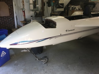
I have built a couple of instrument for canard aircraft and it is always a challenge. Especially for a LongEZ since panel space is a premium and the spacing between the radios.. Here are a few tips to help you with the process.

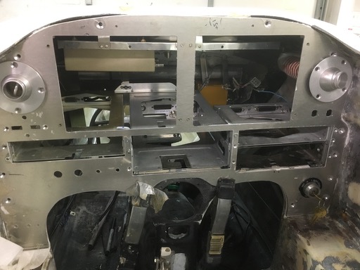
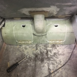
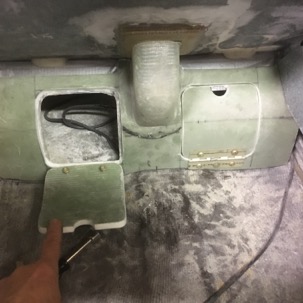
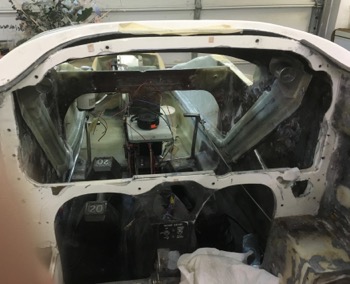
Here you can see where I created a space for the new instrument panel I had to plug a few instrument areas and mounted nut plates on the backside of the perimeter of the old panel. These nut plate will help you index the new panel templates.

IMG_4205-2016-04-4-10-54.jpg

I like using .090” 67061-T6 aluminum. It is easy to machine, stiff enough for the purpose and most importantly, most set backs (exposure ring) of the instruments is designed for a panel of this thickness. You’ll also need a basic computer drafting program (I use Auto-cad) which helps with the design of the panel and some basic hand tools such as a jig saw, drill, rotary grinder and band saw. That it!

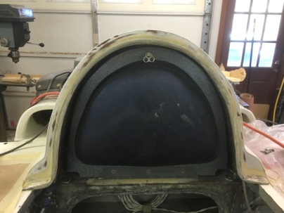
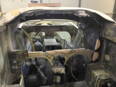
Initially I start with a rough measurement of the panel space to layout out the design of the panel. Don’t worry about the perimeter edges of the panel. That will be done later.

With your basic instrument panel layout on the computer done, get a 4×8 sheet of 1/4” luan ply wood. Cut and trim it to fit in the panel space of your plane. It is much easy to shape, sand and grind to fit perfectly the the AL is. Trying to model the permitter of the panel on the computer is very difficult because our planes are all custom built and a waste of time.

wpid-IMG_4397-2016-04-4-10-54.jpg

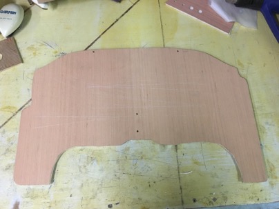
Next step is now that you have the basic panel made, you need to index it to the plane. On this picture you can see two holes at the top and middle of the panel. This panel becomes your your “Master Template”. Transfer drill the alignment holes to the mounting flange. DO not drill permitter mounting holes at this time.

The master template allows you to easily make more copies as needed and it will always fit. The index holes allows you to always place the panel in the same location. It was fairly mark the holes on auto cad, then print 8×11 sheets of paper and glue it to the panel and drill the holes. You never change these hole locations as you modify your drawings or make new panels.

Next. Trace your new panel onto another sheet of luan, cut it out and drill it for your first working copy.

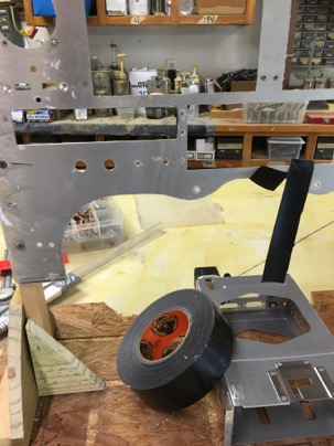
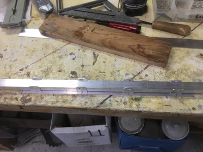
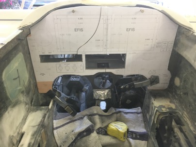
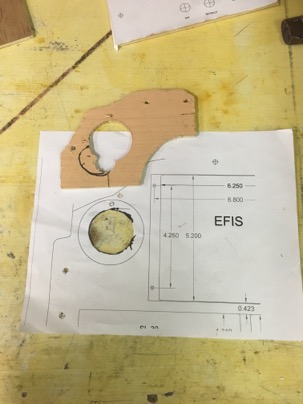
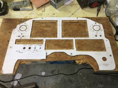
Now you finalize your instrument locations and test design. You can print out individual sheets of paper and glue and tape them to the panel or if you have a wide printer you can make one LARGE printout and glue it to the working copy. I did it both ways and they are equally accurate. Here is the printout glued to the wood for a first look at the layout.

wpid-IMG_4228-2016-04-4-10-54.jpg

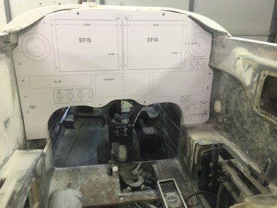
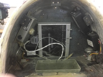
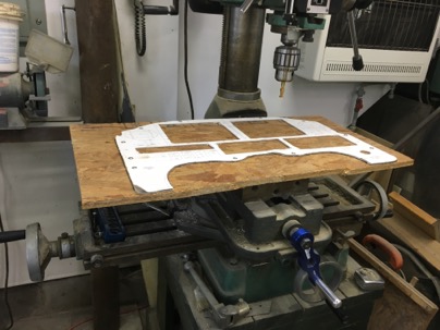
Hum, will the cans fit and was sort to problems to I have going on behind the panel? Yep, I had a number of unseen issues. With a bandsaw you can easily cut the working panel out in a minute or two since you aren’t worried about destroying your ‘working’ panel.

wpid-IMG_4220-2016-04-4-10-54.jpg

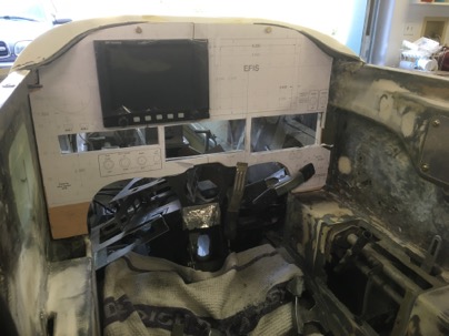
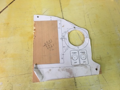
Here you can see I am not even worrying about the perimeter or strength. Just plunge cutting with the band saw to open the holes up. You end up with a panel that has no real structural strength, but will allow you check the fit and feel with the cans lightly placed. LOTS of issues with my first draft.

wpid-IMG_4402-2016-04-4-10-54.jpg

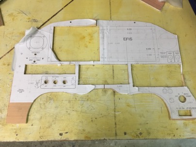
This is the panel pasted together with individual pieces of paper. No strength, just hacked and cobbled together.

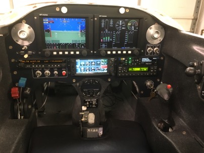
Mount the panel and test fit your instruments.

wpid-IMG_4222-2016-04-4-10-54.jpg

wpid-IMG_4230-2016-04-4-10-54.jpg

Now you have a good idea of interferences and problem areas. I needed to make all sorts of adjustments… such as switch location and vent locations (too high)…first iteration done. Back to the computer for to modify the drawing.

Throw this copy of the panel away, use your ‘master’ and make another copy of the panel as it only takes a couple of minutes to cut it out on the band saw.

Glue your updated paper templates to the new working panel, cut it out …this time I used a jig saw for a nicer panel to see if the radios were a better fit after being moved and they were. Now that I am reasonably happy with the layout, I used this wood copy to drill the perimeter mounting holes in the working copy and transferred them back to the master copy. Use the master copy to NOW drill the permitter holes.

Taking your ‘master panel’, you can trace it onto the aluminum panel and cut out. Transfer drill you holes into the AL. Now place the AL panel in the plane and using the holes as guides, drill all the holes around the perimeter of the panel into the mounting flange. Make your nut planes and flox them on to your mounting flange with screw through the panel. You now have your master panel cut in AL. Now you want to check your switch locations and any other problem areas before cutting up your nice Al work.

NOTE: What is cool about making your panel this way is you can quickly fine tune small sections of the panel. I was a bit unsure of exact locations of the vents opening (due to backside mountings nut plates and switch locations. You can quickly make test panels to how it works for you.

To check your locations, print out that section of the panel on a piece of paper, glue it to a scrap piece of wood, trim it if necessary, and transfer the mounting holes from the master panel to your working panel then test it.

wpid-IMG_4407-2016-04-4-10-54.jpg

wpid-IMG_4403-2016-04-4-10-54.jpg

Had to move the vent holes slight down.

wpid-IMG_4277-2016-04-4-10-54.jpg

Testing the switch distances and heights. Again, more adjustments….

You get the idea, I must have made half a dozen small test panels moving the instruments/switches,/holes slightly up, over, and apart, testing and looking and then correcting the locations on the computer. It is a terrific way of making sure the work you invest making your panel will work fit and be right the first time. Once and done.

This sounds like a bit of effort, but trust me, you dont want to make a mistake on a CNC cut panel because your switches are too close together, or you have some other crazy interference problem. It was very quick to to make the small test sections and test them.

Now you have a final design on the computer but there is just one more step needed prior to cutting it out.

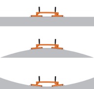
When you mount the blank AL panel and check it with a straight edge, you will find it will probably be twisted slight but it definitely won’t be straight and flat due to the way the flange was installed. You will need to ‘bed’ the panel to make sure it stay straight when all the holes are cut out.

Wax the back of the aluminum, take some WET micro, put a small amount around the permitter and mounting holes, remount the panel and lightly fighting the screws to pull the panel down. Use a straight edge to make sure you pull it flat and straight squishing out the micro and let it cure. In some areas I had to use pieces of wood stir sticks to act as shims until the micro cured. The panel is now bedded and completely flat when the mounting screws are tightened. Yah!!

wpid-IMG_4400-2016-04-4-10-54.jpg

NOW you are now ready to cut the panel out. I think you can do it a number of ways. CNC, using a mill, or a jig saw (my choice). For this panel I used the jig saw first, then cleaned up the lines with a mill. Mostly the mill work was a waste of time.

The paper template protects the AL, and using a jig saw with a light touch will result in amazing straight lines. Center punch the holes for the switches and use a rotary grinder to open up the circles.

I ended up doing a lot of filing on openings anyway after I milled it to size them for the instruments (since each is slightly different), so milling the panel really wasn’t needed.

wpid-IMG_4287-2016-04-4-10-54.jpg

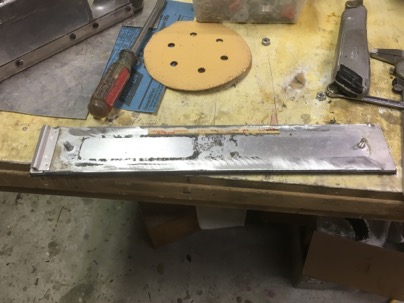
here you can see where I drilled the round holes with a lot of small holes to allow me to use the jig saw to open the circle up. Then using a air grinder with a rotary bit allowed for a reasonable accurate circle, then a 1/2 round final was used. A perfect hole for sure and overall, it took very little time to do. A sharp file cuts this grade of aluminum very quickly.

wpid-IMG_4288-2016-04-4-10-54.jpg

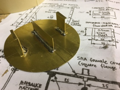
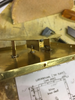
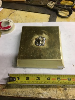
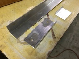
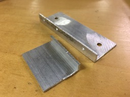
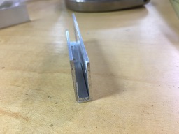
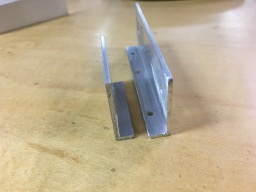
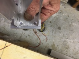
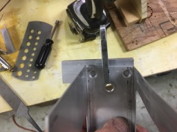
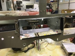
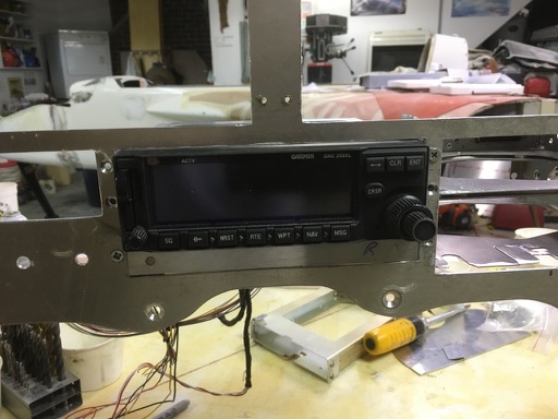
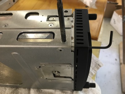
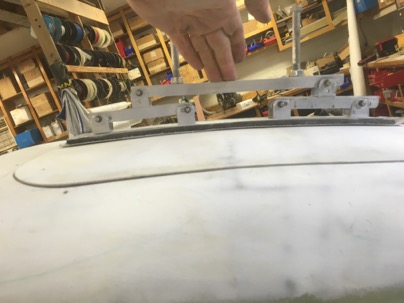
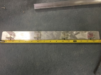
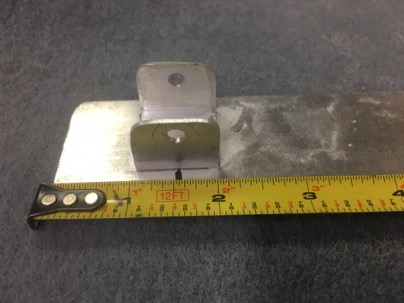
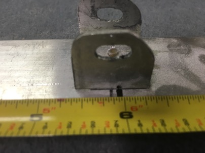
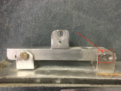
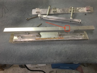
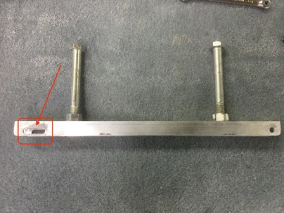
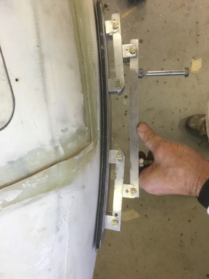
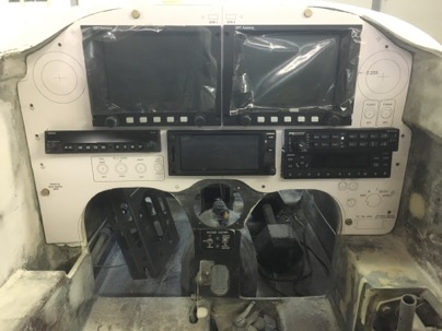
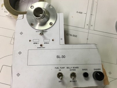
The panel is cut and ready to mount the radio cans. The cans presented a special problem due to the narrowness of the opening between the radios (3/8”). My first attempt to mount the cans turned out to be total crap as all the cans were not level nor straight and wiggled around a bit.

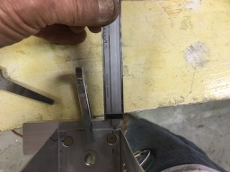
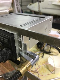
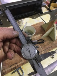
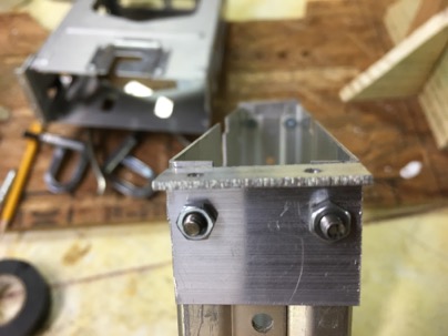
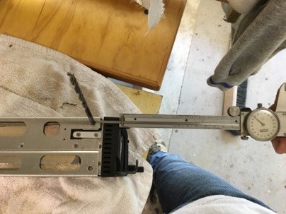
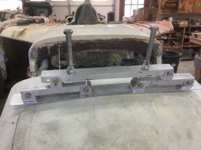
I threw the mounts out, spent some time thinking through the problems and came up with a much better mounting solution which resulted in the vertical alignment at the far end of the cans within 1/16” and the exact desired setback of all the radios to within .500” (+/- .25”) to match my GTR EFIS face place. Straight and level. All the guess work was eliminated and now they are firmly mounted with no movement. Nice.

My next post will detail this technique.

Feb 20 2016

Bridge Sanding/Micro spreading Board

Rarely do I get excited about sanding micro. Especially when it comes to sanding complex curves (curves in two directions such as the nose).

Rubber sanding blocks, cross sanding in different directions, leaves the potential for dips and high spots. Using a long sanding boards aligned to the leading edge of a wing just means you’ll possibly get a long low spot as you work toward the trailing edge unless you carefully angle the board from time to time which leaves the potential of creating a flat spot.

Mike, another cozy builder, turned me on to a sanding board design I have never seen before. I did some research on the net to check out the idea and the concept made amazing sense with tremendous potential. Here is the website with for basic sander design…… .
wpid-11_31_5666f870f05d3_flexisander_nakres_056111_fkk_color-2016-02-20-11-35.jpgwpid-11_8_564c7fe9257f3_ffk_056_uprava_resize-2016-02-20-11-35.jpg

The flexible but stiff base design spreads the sanding pressure evenly over the length of an Al base when you are sanding or spreading micro on a curved surface. Basicity, it is similar to a loading bridge used to test wings for G loading. Very clever!!

Being cheap ( and not knowing how well it would work) I decided to make one for testing. Yesterday I build a couple of flexible bridge boards which turned out to be fantastic for both spreading micro and sanding curved surfaces. I had been using a 10” wide sheet rock mud knife for spreading micro on my wings…. Never again!

All I can say is I love my new sander. It sands curved surfaces perfectly and insures a nice smooth radius since the base is ridge but flexible.. On the nose, it will easily conform to the radius. On a wing you can sand perpendicular to the wing’s Leading Edge and the base will follow the curve of the airfoil to take out any high spot (from traditional sanding), highlight the low spots and will never create a flat spot.. It blew me away when I tried it on a wing.

This is the curve on my nose door. It is very hard to sand to a smooth nice radius this area since the surface curves in two directions.

Front view of my nose using a traditional sanding board
wpid-IMG_4132-2016-02-20-11-35.jpg

This is the bridge sander easily conforms to the surface for a perfectly curve.
wpid-IMG_4134-2016-02-20-11-35.jpg

After just a few seconds of sanding, it was amazing to see how the bridge sander cleaned up the high spots from my previous sanding efforts to sand a perfect curve.

The side view of my nose hatch.
wpid-IMG_4139-2016-02-20-11-35.jpg

The sander curving on the nose hatch. A quick sand again highlighted all the high spots I had missed in the other direction. Sanding at 90 deg both ways forms a perfect compound curve.

wpid-IMG_4140-2016-02-20-11-35.jpg

Overall, making a ‘bridge sander’ was a very easy project (about 2 hrs effort) and most of the material you already have in the shop. AN3 bolts, and rivets. The rest of the materials are available from Lowes for around $15 (enough to make two). A 16” sanding and a 16” micro spreading bridge, or you can order a “real” 16” flexible sander for $104 and a spreading board for $95.

Ok, so how do you make one? Easy. Go to Lowes and buy some cheap Alum and get started. You’ll need:

1” square tubing,
1/16” flat stock
7/8” channel (it fits inside the square tubing).
Some fasteners, whatever you have on hand and rivets.

wpid-IMG_4118-2016-02-20-11-35.jpg

Cut 6 pieces of sq tubing about 1” long

wpid-IMG_4104-2016-02-20-11-35.jpg

Cut a piece of the flat stock about 16” long

4 pieces: Drill a hole though both sides I used a 3/16” drill for the AN3 bolts I had on hand.

wpid-IMG_4120-2016-02-20-11-35.jpg

2 ea: Drill and slot the square tubes. You don’t really need a mill. Just drill a number of holes and file a slot open.

wpid-IMG_4119-2016-02-20-11-35.jpg

Cut the top off of all 6 pieces to create a 1” U channel

wpid-IMG_4121-2016-02-20-11-35.jpg

This is my practice piece… but you get the idea.

wpid-IMG_4122-2016-02-20-11-35.jpg

Clean it up. So now you have 6 U channel pieces, 4 with just holes, 2 with just slots. You have created a bases for the 7/8” channel to slip into.

wpid-IMG_4123-2016-02-20-11-35.jpg

wpid-IMG_4124-2016-02-20-11-35.jpg

Spread the supports bases equal distance on the flat stock. I installed 2 bases (hole only) 1.5” from each end and the slotted bases 6” from each end. That is approx equal spacing along the main part of the base. You can use the 1.5” alum from Lowes, or if you want a wider board for standard strip sanding paper, use .063” AL or G10.

The bases with holes goes on each end
wpid-IMG_4125-2016-02-20-11-35.jpg

The bases with slots are in the center part of the board.
wpid-IMG_4126-2016-02-20-11-35.jpg

Use the 7/8” channel as an alignment tool so all the bases are in a straight line. Drill and rivet the bases to the flat stock.

wpid-IMG_4107-2016-02-20-11-35.jpg

Next cut 2 pieces of 7/8” channel to bridge the distance between the the two bases at each end. Set the channels on the base and drill the cross holes for the bolts. In the slotted bases be sure to drill close to the center of the slot. If you mark and flex the board you will see how the bolt will move when the board is flexed. It will help you decide exactly where the best place is to drill the holes.

.wpid-IMG_4138-2016-02-20-11-35.jpg

Bolt the bridges on the base and again, using the 7/8” channel as a guide for alignment, rivet the remaining U bases with a single hole in the center of each bridge.

Hint: to make it easier to drill and aline the bases, just drill through the alignment channel directly into the bases while they are in the appropriate location. Rivet a drilled base in place then work you way on to the next base, drill and rivet.

wpid-IMG_4130-2016-02-20-11-35.jpg

Lately cut a piece of 7/8” channel for a handle. You will have to make a long slot in one side. Again, the slot is the key to allowing the alum base to bend. In this case, drill one end, assemble, flex the board on a curved surface to mark the limits of the slot. Disassemble and mill/create a slot.

wpid-IMG_4129-2016-02-20-11-35.jpg

The handles are just 2 ea 3/8” bolts I had which are double nutted to the bar.

Here is the bridge sander with a micro spreading base on it.

wpid-IMG_4108-2016-02-20-11-35.jpg

I made a second base from a crapped out in-line sander I was going to throw away. The sander base already had velcro bonded and I had velcro type sand paper on hand for it so I decided to give the sander a new life.

wpid-IMG_4113-2016-02-20-11-35.jpg

It was easy remove the turned up side edges (which made the base stiff) which then allowed the base to flex. It conveniently already had two bolts on it which is perfect for attaching the two end U channels at each end. The mod only took about 30 min to attach 4 each U bases on the sanding board.

Base with side edges lip/ground off.

wpid-IMG_4114-2016-02-20-11-35.jpg

Now I can swap out the spreading board base for a sanding board base using the same handle.

The velcro base bridge sander on the port side of the nose curving toward the tip of the plane.
wpid-IMG_4136-2016-02-20-11-35.jpg

This sander is now become an essential tool for me to quickly obtain an great finish on my plane. Once you try one, you’ll never go back to doing it the old way.

Feb 19 2016

Back Headrest Completed.

I have completed the modifications to the back head rest area. It will make wiring so much easier, allow easier maintenance and allow me to move the my tools to the front of the plane.

The headrest now contains the Llightspeed electric ignition, MAP sensor, starter solenoid, 2 fuel probe modules, the voltage regulator, a ground block, 2 fuse panels

wpid-IMG_4102-2016-02-19-21-11.jpg

and the battery                

wpid-IMG_4101-2016-02-19-21-11.jpg

and the Engine Information system.

The two bolts above the battery serves to retain the battery and allows me to charge or jump the battery without removing the the panel.

wpid-IMG_4146-2016-02-19-21-11.jpg

When not needed the back headrest covers the equipment.

wpid-IMG_4103-2016-02-19-21-11.jpg

Feb 16 2016

Foot panel

I built storage bin for the back seat. I did this on another airplane and it worked out extremely well. I could put a few tools or whatever in it.

It also allows the passenger to have a foot rest.

wpid-IMG_4094-2016-02-16-21-02.jpg

Here is it installed in the back seat which also covers the electric speed brake motor.

wpid-IMG_4147-2016-02-16-21-02.jpg

wpid-IMG_4148-2016-02-16-21-02.jpg