Wiring has begun
This has not been a busy of a week for me. I was sick the first part of the week and with Thanksgiving thrown in, the work on the plane slowed a bit. I was able to complete a few items. I built a O2 bottle support which came out very nice. The bottle is the same size as a 4″ PVC pipe which I used as a form to lay the glass on.
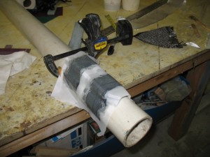
Attaching the support for the closure clasp.
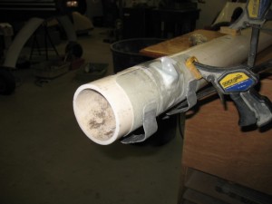
Finished. Painted flat black.
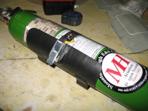
Insturment Panel
I have changed the plan a bit and now want a carbon instrument panel. Quite a few hours this week was spent finalizing and rechecking the Acad drawing so it can be cut out on a CNC machine in LA. I should have a test panel in a week or so. After I finish installing the supports and lettering it, the panel will go back LA for clear coating and polishing.
WIRING
I also started working on the wiring system. I have been avoiding the wiring just becauseI know how much work it is truely going to be. Many, MANY hours sitting at the computer drawing and documenting the wiring harness. After installation, there will be many hours of correction the drawing for final printing. I laid out all the major electrical components on my spare bed and looking at all the wiring ahead is daunting!
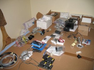
The wiring diagrams are absolutely CRITICAL to long term maintenance of the plane and they need to be as complete and clear as possible. After flying these planes for years, I find most of the maintenanceissues in the future will mainly be wiring problem. Fixing a screw, bushing or engine component is quick and easy. Finding out why a light or radio stops working is really tough and almost impossible without a well documented wiring schematic. The type of connectors, switches, plugs, type of crimper used, wire, etc should be of the highest quality possible, because it will bite you in the butt if you dont pay really close attending to this critical aspect of the plane. Of all the work I am doing on the plane, I approach this area with the greatest concern and closest attention to detail possible. This is why it takes so much time and effort. I spent 3 hrs yesterday working on just 4 pages of wiring and I am still not done. I will probably have 30 or 40 drawings.
Some people approach the electrical draw from the aspect that you should put everything in an area on one page. An example is the power system should show all components and where they all go (charging, starting, lights, lines to the radios, etc). This is great for wiring the plane, but doesn’t help as much when you are trouble shooting a sub area of the larger system. Lets say you are only working on the alternator part of this system.
I like drawing the areas out in sub systems. The alternator system is drawn separately from the starting system or the ignition system. In the future when you are trouble shooting problems with the charging system, it is MUCH easier to look at just the system of interest and visually see what is going on. You dont have to separate it from a larger drawing with lots of other stuff on it. It makes wiring the plane more of a pain but is much easier to trace wires.
Anyone can wire a plane… it is not rocket science and is fairly easy to do. Run a wire from A to B and you are done. Easy. I have seen so may planes (certified and experimental) where if you ask the owner for a wiring diagram, you’ll get a blank stare. I have seen very few few wiring diagrams and they were by obsessive compulsive engineer types who really knew the value of having one. Most builders just wing it. I had to rewire my plane because of a crappy wiring job and no documentation and did a fair job drawing out the wiring on Tweety. On this plane, it will be the mother of documentation because I plan to reuse most of it on my cozy 4 (Bubba) so it is worth the extra effort. Beside, I want to do it right for myself .
Wire Zip Loops Ties
One thing which has always bothered me was how do you attach the wire bundles to the plane. In my plane I used click bonds with Adel clamps which are heavy and awkward to use. I wanted something easier to install and more versatile. So I made up some attachment point I call bow-ties.
First I layed some glass over some small diameter rods.
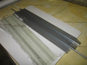
After slotting the glass layup (I used a radial arm saw), you can cut them up into individual loops or as strip and flox them to the surface of the fuselage. A zip tie to hold the wire bundle to the bow tie and you are done. I weighed a single zip loop and it works out to .5 grams each. What I like about it is if you wish to have a number of separate wire bundles (my favorite choice) you can cut a strip of zip loop ties and flox them down as a group. Then the wire bundles are equally spaced out along the wire run.
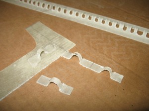
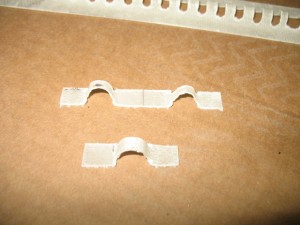
I think may make another strip of ties which will improve my original design. The first set used a rod as the form and was a very easy way to make a strip of bow ties, but the top of the ties is rounded and a bit taller than I want. I plan to make a gig which will be squared on the top (3/16″) about 1/4″ high and use 2 layers of carbon. It will hold the zip ties better and I have plenty of scrap materials around to try it out.