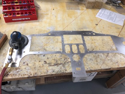
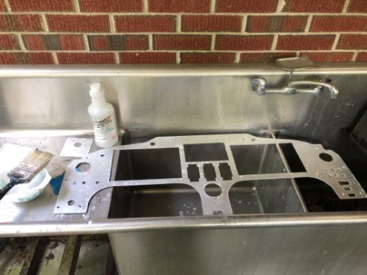
Today was spent preparing the plane structure for accepting the instrument panel.
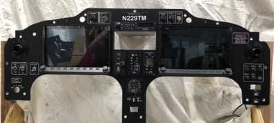
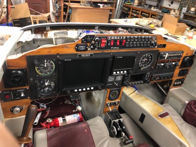
The panel was temporarily installed and all the switches and equipment was installed to make sure the clearances were ok in the old instrument panel.
I really like the way the panel came out and look forward to flying with it.
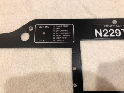
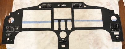
I forgot to add the passenger warning, so I called the vinyl print shop and they printed this out for me the same day. Using vinyl lettering really speeds up the process of fabricating the panel.
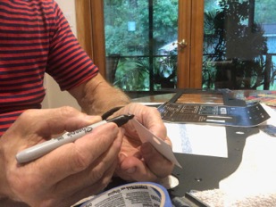
The lettering came out really nice and was really easy to do.
Here is a little trick when applying the lettering.
The decals are printing on a matt white base vinyl with black (or any color printing). Most print shops will accept a .pdf file of your lettering that you designed.
After cutting out your graphic, be sure to use a black magic marker to color the edges of the white vinyl base layer. This will prevent you from seeing the white edge of the base layer..
This is a close up of the lettering on the panel. An easy way to place the decals is to position them in the right location. Use some masking tape on one side to make a flexible hinge. Fold the decal back to remove the backing and carefully fold the decal back over to apply. The hinge will keep the decal aligned for an exact placement.
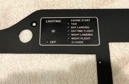
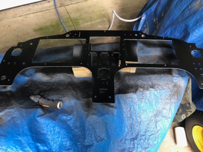
This is how the panel will look after the lettering is installed. After the decals are applied, the next step is clear coating the panel to seal everything permanently in place.
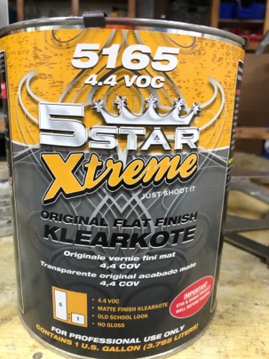
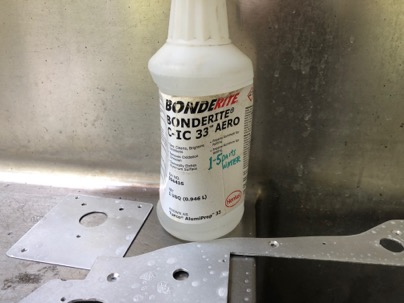
For clear coating, you want to use any automotive clear coat, but I like a matt finish. You can use a glossy clear coat and add a flattener (from your paint supplier) to give you the matt finish. In my case I used a clear coat with the flattener already added to it.
Uncategorized | Nick | Comments Off on Applying the vinyl Lettering to the panel
Installing the radio cans is simple and straight forward, but it does require a little thought into what kind of presentation you would like to display.
Typically, radios are installed with the fascia of the radio on the surface of the panel. Trying to just drill holes in a side plate is harder than one might think because of alignment of each side, trying to be perpendicular to the face of the panel, and where the mounting holes are in the cans (the are all different).. I find this method unacceptable because additionally, each radio or piece of equipment has a different depth of its face which (to me) unintentionally makes the panel look a bit disorganized with each piece of equipment just sticking out into the cabin a different amount.
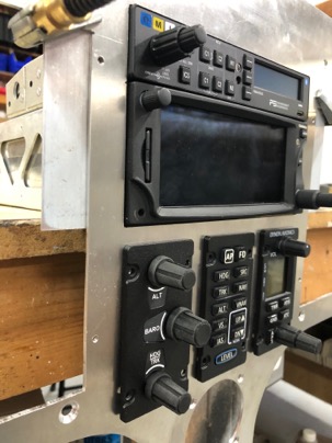
I prefer to recess the cans into the panel to provide the exact amount of exposure necessary so all radios and equipment have the same exposure height for a nice organized look.
Actually, I found a very easy and fast technique for installing the cans which also ensures all the cans are perfectly perpendicular to the face of the panel. Once you decide on the amount of radio exposure desired, use this method to mount the radio cans. This is post from April 2016 when I used the same method for mounting the cans in my LongEZ. http://nickugolini.com/blog/?s=panel+mounting
Personally, I prefer using rivets instead of screws to attaching the cans to the side brackets which prevents any movement of the cans
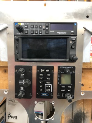
Radios in place to check for the look I want.
Normally the Garmin has a .850” exposure. The Audio panel had a .780” exposure which would be a .070” mismatch. The Dynon sub panels have a .150” exposure. Here you can see how far I have recessed the radios into the dash everything lines up perfectly. After installation, all the exposures were within .020” of each other.
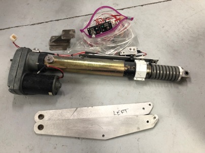
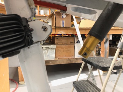
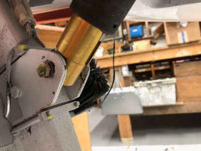
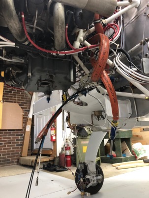
I decided to remove the Wright nose lift and replace it with a new Wilhelmson EZNose lift. I find the EZNoselift to be more repairable, smaller, lighter with better features (automatic extension).
The only major issue with the installation is the Wright nose lift uses a -5 bolt and the EZnoselift uses a -4 bolt.
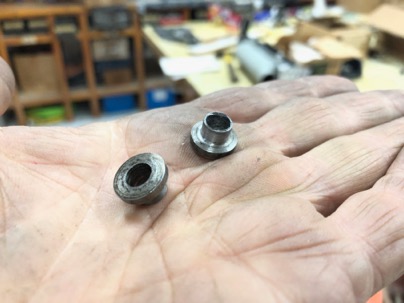
The easy solution was to machine a couple of reducer bushing.
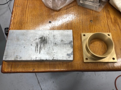
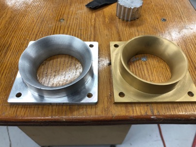
When I received the rebuilt Bendix throttle bottle from Airflow Performance (AFP) I also order an air filter and the flow guide to attach the filter to the fuel servo.
he strange thing is the flow guide has a 3.25” flange and the K&N filter they sell requires a 3.5” flange. I ask AFP what I should do and they really didn’t have an answer for the issue. I was told to just cut a piece of PVC pipe and use the ring as a spacer to fill the gap… Yikes! do people real do that sort of thing on their planes?
Amazingly, I happened to have some 1” AL stock of the right size and decided to machine my own flow guide.
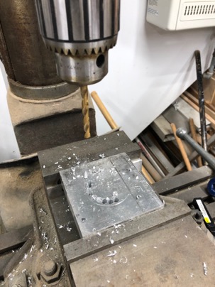
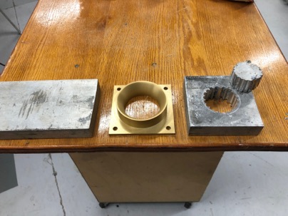
That 1” AL is really thick and difficult to work with. After cutting the block off I needed to remove the center to make a hole.
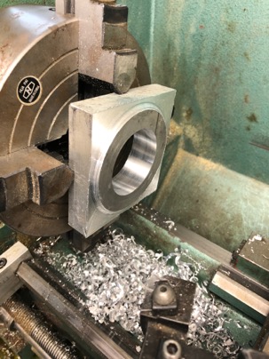
Next is is spending a bit of fun time on the lathe.
Four hours later, I had a new flange with the 3.5” flange I wanted which was basically free. Now I’ll return the $135 air inlet back to AFP.
Today I started removing at the Ellison throttle body fuel system with the primer and facet pumps. I also sent the entire Bendix system to Airflow performance for overhaul.
Fuel System | Nick | Comments Off on Fuel Injection Installation
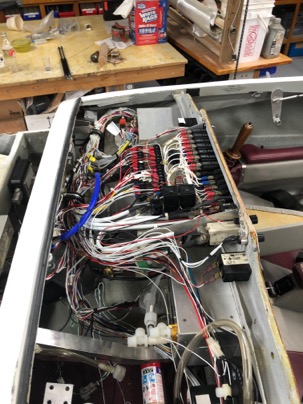
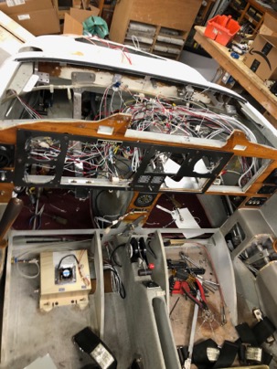
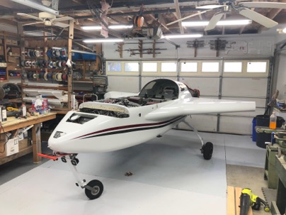
Today I started on removing the wiring from the plane. I wanted to preserved some of the original wiring (starter, ignition, etc).
A nice looking instrument panel. I wold the entire panel to Spencer for a cozy 3 project he is working on.
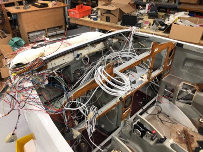
I decided that I wanted to wire the plane differently and with the installation of the Dynon SkyView system, the harnesses will be completely different. I felt it was better to replace everything.
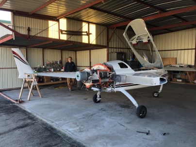
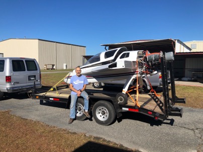
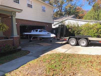
A very dear friend, Roger was instrumental in helping me remove the wings and he bought over his large trailer to transport the plane to my shop.
Tomorrow I’ll begin disassembling the plane’s electrical system which will be a little challenging because I want to preserve some parts of the system such as the ignition and charging systems, while removing most of the rest of the dash and electrical wires and instrumentation.